


Other Parts Discussed in Thread: FDC2114
I'm using the FDC2114 evaluation module to test the FDC2114 chip to use it in a material thickness sensor.
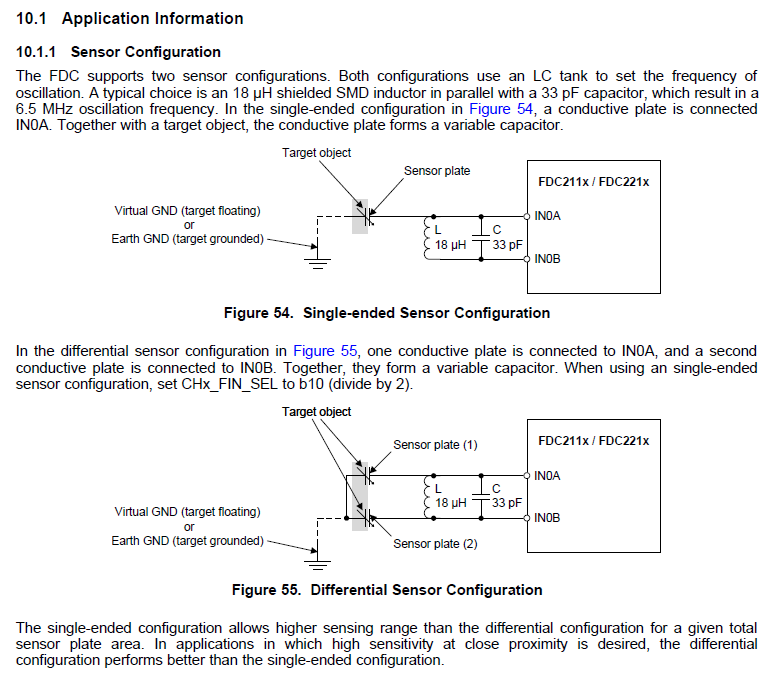
Following the page 39 of this document i can see the two configurations that i can connect my sensor to the input pins.
Actually the connection of my sensor is like the picture below, but i'm not sure if is the correct way that do it.
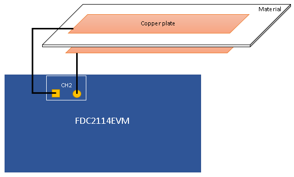
The measures of the capacitance changes that i've done maybe reasonable but the sensor capacitance is not equal to the theorical value.
Another question is where would the GND be and if it should be connected to the common GND of the module?
Seeing the examples of application like the fluid levels is more claire, but in my case i think that it is not.
Any help would be much appreciated
Best Regards
Kevin

