This thread has been locked.

If you have a related question, please click the "Ask a related question" button in the top right corner. The newly created question will be automatically linked to this question.

DCA1000EVM: How to use the 'Start Chirp For Cfg' and 'End Chirp for Cfg' in Chirp sub tab? How to use the 'Start Chirp TX' and 'End Chirp TX' in frame sub tab?

Part Number: DCA1000EVM

Hello, everyone! I met with some problems when I used the 'mmWave Studio 2.0.0.2'.I would be grateful if you could help me.

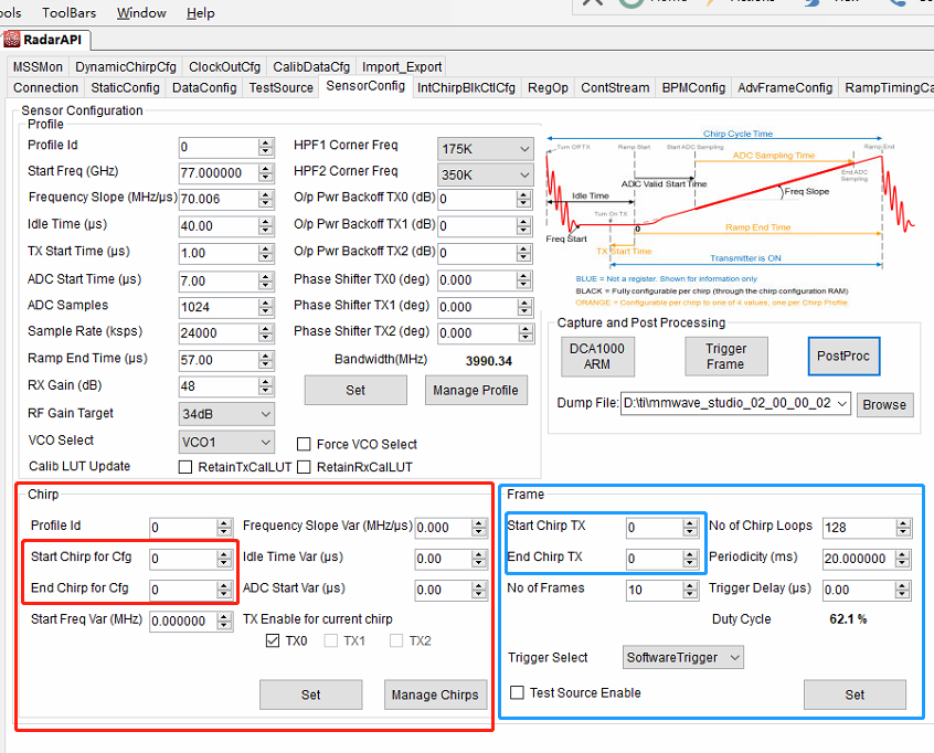
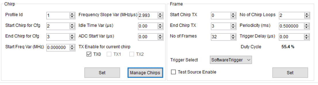
1 How to use the 'Start Chirp For Cfg' and 'End Chirp for Cfg' in Chirp sub tab?

2 How to use the 'Start Chirp TX' and 'End Chirp TX' in frame sub tab?

3 Can you tell me the relationship between the Chirp tab and Frame tab?

  • Hi,

    Every chirp has a Chirp Index and every chirp is associated with a particular profileID and 0 or more TXs enabled, along with the StartFreqVar, FreqSlopeVar, IdleTimeVar and ADCStartVar parameters. You can configure many similar chirps together by using the AWR_CHIRP_CONF_SET_SB API (or equivalently the chirp configuration group box highlighted in red in your screenshot).

    To do this, you would specify a starting index and ending index for the chirp. For example, to configure 10 chirps starting at chirp 0, you will select Start Chirp = 0, End Chirp = 9. Then these ten chirps will have the same parameters (like ProfileId, StartFreqVar, FreqSlopeVar, IdleTimeVar, ADCStartVar and TXEnable.

    Every frame consists of a sequence of chirps looped multiple times. A frame is specified by the AWR_FRAME_CONF_SET_SB API or equivalently the Frame Configuration group box highlighted in blue in your screenshot. The frame will start with the chirp index marked as "Start Chirp TX" and End at "End Chirp TX", and this sequence will repeat "No of Chirp Loop" times.

    Please refer to the AWR1xxx Radar Interface Control Document released as part of the MMWAVE DFP package, and also to the application note "Programming Chirp Parameters in TI Radar Devices" available here: www.ti.com/lit/an/swra553/swra553.pdf

    Best Regards,
    Anand
  • Hi Anand,

    As you mentioned above, when I set up as fig 1.2, the result is fig3.
    So, in fig3 I should understand (where yellow) that config is chirp and chirp is the number loop. in fig4 is a frame and there are 32 frames repeated.
    Can you tell me how to calculate the periodicity of the frame?
    fig1
    fig2
    fig3
    fig4
    thanks you
    BUI GIAP
  • Hi,

    Yes, you are correct that in figure 3 "Config" is the different chirps, and "Chirp" is the number of chirp loops.

    Each chirp duration is the idle time of the chirp plus the active time of the chirp. These times are defined in the profile associated with each chirp plus any additions made in the IdleTimeVar field of the chirp configuration itself.

    You have four chirps in figure 2 looped two times (total 8 chirps), two of them associated with Profile 0 and the other two with Profile 1. So you would add up the idle and ramp end times of these chirps to get the total active duration. Additionally, we need at least 250 us per frame. (See the AWR_FRAME_CONF_SET_SB in the ICD document for these numbers).

    The frame periodicity should be configure to be greater than the active frame duration (plus 250us). This is the period of one frame.

    Note that the 32 frames that you have configured does not affect this periodicity - the total duration of chirping will be 32 times the configured frame periodicity.

    Best Regards,
    Anand
  • Anand

    I understood my problem.

    Thank you for your reply.

    BUI GIAP

  • Okay, I will close this thread then. Please reopen another one if needed.

    Please tick the "This Resolved My Issue" button if the above reply helped.

    Best Regards,

    Anand