This thread has been locked.

If you have a related question, please click the "Ask a related question" button in the top right corner. The newly created question will be automatically linked to this question.

AWR1642BOOST: AWR1642BOOST : ADC raw data capture using CCS Capture Demo; Teraterm not showing Capture Demo options

Part Number: AWR1642BOOST
Other Parts Discussed in Thread: UNIFLASH, AWR1642, DCA1000EVM, AWR1243, SYSBIOS

Hi,

I am a new and basic user of mmwave AWR1642BOOST. I am trying to get acquainted with it, I have observed some serious difficulties with the TI documentation but i will share my feedback later on when I will spare some time. However, at the moment, I will just say that TI seriously needs to revamp its mmwave sensor documentation as many persons like me are forced to waste considerable time on very basic things that should have been clearly included in the documentation.

As a result, I can see that TI support team is also forced to invest huge amount of time in responding to a large number of customer inquiries that could have been avoided if the documentation was well prepared.

I have been working fruitlessly for one week on issues with AWR1642BOOST and you can probably feel my frustration also, my apologies for that.

But, I will indeed submit a detailed review of mmwave TI documentation for your perusal.

At the moment, my issue is that I am trying to get ADC data from AWR1642BOOST EVM Rev B. I am using CCS 7.4 and mmwave sdk 1.00.00.05.

I am facing exactly the same problem as mentioned in the following TI E2E thread:

https://e2e.ti.com/support/sensors/f/1023/t/738304?CCS-AWR1642-Raw-ADC-data-Capture-Demo

 I have been following the same steps, except the following differences:

1. After step 1, I am using CCS to upload files to dss and mss as mentioned in para 2 of section 3.3.2 of mmwav sdk user guide rev 1.0.0. (file attached).

http://e2e.ti.com/cfs-file/__key/communityserver-discussions-components-files/1023/mmwave_5F00_sdk_5F00_user_5F00_guide-1.0.0.pdf


After that I run the C674 and R4F cores

2. I am using teraterm for COM port communication. I select the correct COM port and set the correct baud rate i.e. 115200.

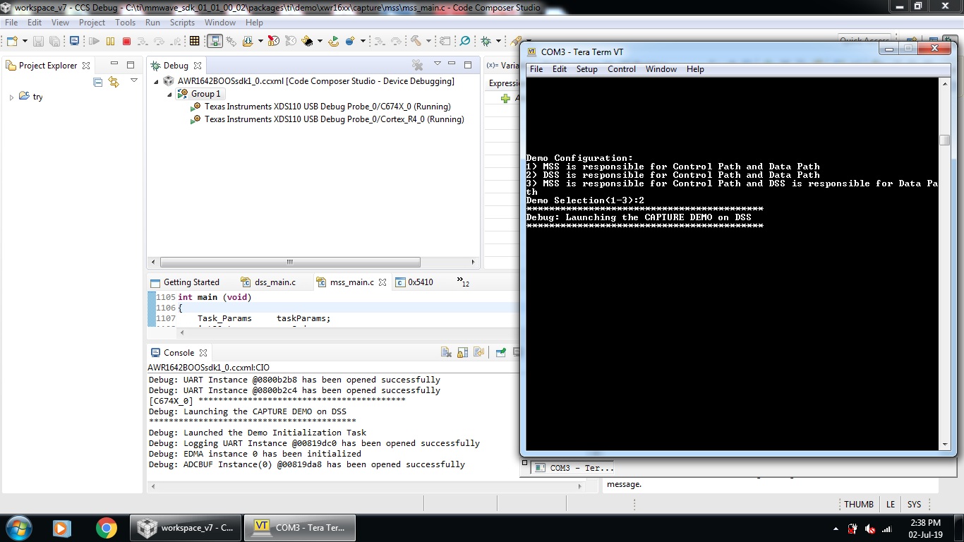
The selection appears at the Tera term window. However, as soon as I select option 1 or option 3, nothing more appears on the screen even if I hit enter again.

TI official Kyle Cousino has advised in the previous related thread that the steps are correct except that:

" Once you get to step 3 in your process, you need to copy the contents of this file into your CLI program:

C:\ti\mmwave_sdk_01_01_00_02\packages\ti\demo\xwr16xx\capture\capture_demo_script.txt "

My question is :

1. Can you please have a look at the steps I am following and tell me how can I possibly move forward ?

A very basic question, refer the suggestion from Kyle above in red, can you please tell me where exactly do I need input the text of configuration file ?

If i need to input that text into Teraterm window then it is not working, there is just a pointer there. Following is the screen shot of what I am getting :

2. After that, I need to select memory capture procedure as per para 5 of section 3.4.3 of relevant attached sdk user guide, but so far I have not been able to reach that point.

Thanking you in advance.

  • Hi Alper,

    I understand your frustration here. We would appreciate your feedback on documentation which helps us to improve the product.

    Now to your issue, I assume you are using SDK 1.1 version which is not supported now. mmWave SDK 1.2 is LTS (long term support) version.

    Even if you need to use SDK 1.1 version, could you try building the capture demo at your end (follow the user guide for building steps).

    In case of option '3' it won't ask for input from Terminal, and DSS will execute with the inbuild configurations.

    Regards,

    Jitendra

  • Hi Jitendra,

    Thanks for your reply.

    I need to clarify a few things :

    1. In your reply above, you have stated that SDK 1.1 is not supported now and SDK1.2 is LTS (long term support) version. Does it mean that TI cannot support / advice on issues related to SDK1.1 ? Please comment (although I am thankful that you still gave advice).

    2. Whether the answer to above question is yes or no, I will again ask a basic question, irrespective of SDK version. At the moment, my issue is that I am trying to get ADC data from AWR1642BOOST EVM Rev B. I am using CCS 7.4 and mmwave sdk 1.00.00.05. (Even if it is related to SDK version, I request guidance on it, if possible).

    I understand that in this case, the commands are given to AWR1642EVM by CCS and not by SDK so SDK version is not important..

    I am not using SDK (no matter which version). I again refer the link below:

    https://e2e.ti.com/support/sensors/f/1023/t/738304?CCS-AWR1642-Raw-ADC-data-Capture-Demo

    TI official Kyle Cousino has advised in the previous related thread that the steps are correct except that:

    " Once you get to step 3 in your process, you need to copy the contents of this file into your CLI program:

    C:\ti\mmwave_sdk_01_01_00_02\packages\ti\demo\xwr16xx\capture\capture_demo_script.txt "

    A very basic question, refer the suggestion from Kyle above in red, can you please tell me where exactly do I need input the text of configuration file ?

    If i need to input that text into Teraterm window then it is not working, there is just a pointer there. Following is the screen shot of what I am getting :

    OR do I need to input the CLI commands in CCS, if yes, then where ?

    3.  My basic requirement is that I only have AWR1642BOOST EVM and I wish to see the raw ADC outpur data (note I dont have DCA1000 EVM or TSW1400 EVM). At the moment, I just need to see that data, however later I will need to post-process it.

    a. Is there any way (possibly with latest SDK versions like 3.1 or 3.2 or some other version of SDK (except the ones with csv support)  that I can see the raw ADC data (possibly not in real time even). If yes, then how ?

    If there is any such possibility, I do not need to use SDK1.1 OR mmwave mmwave sdk 1.00.00.05.

    b. I understand that I can only post-process the raw ADC data after I get it on LVDS from DCA1000 EVM. Is my understanding correct?

    4. In the meanwhile, especially if answer to question 3a is negative, then I will try to act upon your advice on trying to build my own end but my question is that why should I need to build demos at my own end when I suppose (if I am not wrong) that the relevant demos are already available in mmwave sdk 1.00.00.05 (refer para 2 of section 3.3.2 of mmwav sdk user guide rev 1.0.0. (file attached).

    http://e2e.ti.com/cfs-file/__key/communityserver-discussions-components-files/1023/mmwave_5F00_sdk_5F00_user_5F00_guide-1.0.0.pdf

    Note that I do not intend to change the demos, I just want to run them capture demo as it is. Therefore, I think I do not need to BUILD the demos at my own end. Is my understanding right ?

    I am sorry for the complex questions but I request a point-wise guidance on each individual question.

    Thanks in advance.

  • Hi,

    I do not feel that my query is addressed.

    I request to please address and reply to my latest message, although I realize it might be complex.

    But at the same time, I feel that a to-the-point and concise guidance from TI can get me through.

    Best regards

  • Hi TI Team ,

    Can I request again a feedback to my above query dated 24th June, 2019 please ?

    Regards

  • For question 2: "If i need to input that text into Teraterm window then it is not working, there is just a pointer there."

    From my understanding when they say " Once you get to step 3 in your process, you need to copy the contents of this file into your CLI program: C:\ti\mmwave_sdk_01_01_00_02\packages\ti\demo\xwr16xx\capture\capture_demo_script.txt " as you noted, they literally mean to copy an paste each line of code provided into the terminal as you should be able to input commands. 

    That being said, I am having the same problem you are where the terminal completely freezes after selecting any option (1, 2, or 3).  According to the user guide documentation provided with the 1.1.0.2 SDK (which is what I am trying to use to do the same thing) section 3.3.3 #3 says:

    " For mode 2(DSS only mode), there is no configuration CLI. All configuration parameters are hard-coded in the code and are same as seen in the capture_demo_script.txt."

    This leads me to think that running option 2 would not require configuration, however, after attempting to run this several times, following the steps provided in the documentation does not yield any information after connecting to the device using CCS.  I'm not sure if you have tried option 2 to test this theory or not as I see in your screenshot that you tried option 3.

    Long story short, try reflashing and connecting via the command line, then connect via CCS and check the values stated in section 3.3.3 5) c. of the Expressions Window.  Let me know how this goes, or if you find any more information out, but I am getting an error from CCS (probably because the command line is frozen):

    Break at address "0x7fec54" with no debug information available, or outside of program code.

    Following that code takes me to this line:

    007fec54:   1004C812            CALLP.S2      0x801280 (PC+9792 = 0x00801280),B3

  • Dear Brent Kuhn !

    Thanks a lot for writing . . . .I am truly grateful . .. 

    I wish me and you succeed and get out of this fruitless errand so far that has consumed my three weeks so far and how much more is to go, I dont know . . . 

    Well, I will write what I have done so far.

    1) Although I think that I did not need to do that and SDK provided binary files would have enough for me, yet as per the advice of TI official, I re-built the binary files for C674 and R4F and loaded them in capture demo using CCS. Still there was no success.

    2) After reading your reply today, I installed and worked with sdk version 1.1.0.2 (earlier I was working with 1.0.0.5). Same story here, no success.

    3) I will take advice from TI in another new question/thread that why have they removed capture demo from SDK. It was seemingly a good option for those who only had xWR1xxx EVMs and who did not / could not use TWS1400 or DCA1000 EVMs for LVDS connectivity. (May be a TI official can comment here as well . . . .)

    4) I now understand that the CLI commands need to be given on COM port interface (e.g. Teraterm) but I am unable to do that as Teraterm freezes.

    5) Yes, for DSS (option 2) (as per 3.3.3 #3 of SDK User Guide 1.0.0 (Oct 2017 Release), applicable to SDK version 1.1.0.2), the CLI commands are hard-coded and we cant/need not to input those commands. I tried that and had partial success. Refer the screen shot showing CCS and Teraterm windows superimposed.

    5a) However, the success was partial. Refer 3.3.3 # 4 of applicable SDK User Guide. I did not get prompt for selection of "Memory Capture" or "Streaming over LVDS" selection.

    5b) I still further attempted action as pera 3.3.3 # 5c, The memory address for ChripIntCounter does not match with the given counter value (0x80).

    6) My latest attempt was with option 3 again with SDK 1.1.0.2; earlier numerous attempts with SDK 1.0.0.5 (with and without re-built binaries) produced same result.

    With SDK 1.1.0.2, when I selected option 3 on Teraterm, I got the following (error) messages on CCS console.

    I think the main cause is XDC. I was suspecting this so I tried, both the latest version of XDC and the version mentioned in SDK release notes while I re-built the binaries for C674 and R4F, but still no success in both cases. The same XDC error appears every time.

    May be you can comment or add some thing ?

    Best regards

  • I have been using CCSv9 to attempt to debug this, which unfortunately doesn't seem to let me import the project, so I could not rebuild the binaries.

    I reflashed my board using the xwr16xx_capture_demo.bin and xwr16xx_ccsdebug.bin as the two meta images using uniflash.  This allowed me to use the debug mode which it looks like you are running now.

    I was using PuTTY instead of terraterm (just a personal preference), however, there is also a terminal in CCS which would allow you to communicate with the device while in debug mode.  Maybe this will be more fruitful for you than it was for me considering I received the same failure at the same point, however, you can see in the bottom right-hand corner of the below image that I opened a terminal with the device after connecting to it in debug mode.  This seemed promising considering only one application is really capable of being connected to a serial device at a time.  Running this terminal while in debug mode also allows you to see real-time errors as they occur while communicating with the board over the serial connection.

    I also uploaded the xwr16xx_capture_demo_dss.xe674 and xwr16xx_capture_demo_mss.xer4f to their respective processors as noted in 3.4.3 5 b) of the sdk user guide, and opened the memory browser and jumped to the 0x51020000 location which is where the data should propagate if the demo runs properly.

    All this being said, the demo using UART only communicates one single frame of data (which is a small amount due to UART being slow -- exact values in the documentation), and after much forum reading, the reason it has been removed from later versions of the SDK is due to the fact that the DCA1000 FPGA was designed to transfer this data semi-continuously.  I am currently in the process of investigating if the device is worth the purchase as my institution is willing to purchase it if I can see that it will be beneficial to our work.

    Hopefully, any of my above data-dump will help you out, and despite possibly acquiring a DCA1000 I will continue to attempt to get this demo working until I actually have that device in hand, so I will be back if I get any closer to a solution.

  • Hi,

    If your requirement is to capture the raw data from AWR1642 device then I recommend you to use mmWave Studio and DCA1000EVM where you don't need to flash any binary to device or even load from CCS. That will ease your task to capture the raw data.

    http://software-dl.ti.com/ra-processors/esd/MMWAVE-STUDIO/latest/index_FDS.html

    Follow the mmWave Studio user guide and DCA1000 quick guide pdf where it explains how to use Studio with DCA1000. This tool is mainly for AWR1243 so most of document revolve around the same device but if using AWR1642 then only difference will be selection of firmware which needs to be loaded to device in SOP-2 (development mode).

    These firmware you need to use in case of AWR1642 : rf_eval_firmware\masterss\xwr16xx_masterss.bin (for MasterSS) and rf_eval_firmware\radarss\xwr16xx_radarss.bin (for RadarSS/BSS). And make sure you have erased the sFLash before using with mmWave Studio.

    Even after this if you need to use SDK based application then I would request you to use SDK 2.1 onward versions which we support. In 2.1 / 3.1 / 3.2 version we have equivalent capture demo which you can find at this directory (<sdk installation path>\packages\ti\drivers\test\mem_capture).

    Regards,

    Jitendra

  • Hi Brent,

    Hi Jitendra,

    Thank you for your above messages, guidance and suggestions.

    Both of you gentlemen, please offer your comments / advice on some or all points above, if possible and if needed.

    Jitendra, I understand  that support it available for older SDK versions but the following may be considered relevant to new SDK versions as well, so your valuable comments will add a lot of value.

    The following is sort of LATEST (BUT INTERIM) STATUS UPDATE, which I am sharing so that it may help someone else like me who is/will face similar issues:

    1)  Why I need Capture Demo with for ADC data capture : I understand that TI developed DCA1000 EVM for facilitating continuous acquisition of ADC data on LVDS mode. However, the fact is that AWR1642BOOST costs 300 USD and DCA1000EVM costs 500 USD and in some countries, additional Custom duties might be levied. It is also a fact that many persons probably would not be in situation to afford DCA1000EVM but would definitely like to first explore the possibilities first with AWR1642BOOST EVM (or like). 

    Nonetheless, some 6 months ago, we arranged some money and ordered one AWR1642BOOST and one DCA1000EVM through a country representative of Mouser. Unfortunately, the DCA1000EVM was faulty. We spent almost 4 months in trying to get its replacement (we now expect to get it but I will only be sure when we get it in our hands).

    So now we could not order immediately another DCA1000EVM. In the meanwhile as we were struggling to get its replacement, we tried to experiment and study to the extent possible with the AWR1642BOOST only. In this regard, we also wanted to see, read and understand raw ADC data (even in offline mode) to understand the device working and data format. We knew that we could not process it in real time but with ourselves being handicapped now due to faulty DCA1000EVM, we wished to work with whatever data that could be obtained from AWR1642BOOST.

    Moreover, we wanted to bypass any intermediate processing and we wished to obtain the data (to the extent possible) directly from the radar output.

    The above were the reasons for which we wished to have raw ADC data.

    When we looked for this data, I found that the Demo Visualizer was saving it in a DAT file, however I found that it was not readable. On further exploration, I found that some script (may be in MATLAB or Python) would be needed for that.

    At the same time, I came across the old questions in the TI bog from where I learnt that in earlier versions, there was a Capture Demo and after spending still more time, I learnt that Capture Demo was removed from the later versions of SDK.

    In view of above, I strongly recommend and suggest TI that Capture Demo may please be included again in the latest SDK version although I understand that it has frame and memory limitations. But, still, it will be much helpful for many customers who only have xWR1xxxBOOST EVMs.

    2)  However, I will still try SDK 2.1 (or above) as suggested by Jitendra. I have seen that it has a mem_capture demo in the location advised. At this time, can you please just advise that:

    2a)  Which file do I need to install as Metaimage for running the mem_capture demo available at the location (<sdk installation path>\packages\ti\drivers\test\mem_capture) for SDK versions 2.1 and above ?

    2b)  Can TI please advise that why mem_capture demo is put as Test and why it has been removed from the main demo ? Does the mem_capture has the same/identical functionality of original Capture Demo or does this newer mem_capture demo (Test) have certain limitations in comparison with original old Capture Demo ? If yes, then what are those limitations ?

    3) I think that you can build binaries with CCSv9 as well even if CCSv9 does not allow you to import projects (though I have not installed CCS 9, but I wonder why CCS 9 does not allow to import Projects). Nonetheless, for building the binaries, you do not need to import any project. You can use and follow section 4.4 of SDK User Guide (Product Release 1.0.0) for SDK 1.0.0.5 or section 4.5 of SDK User Guide (Product Release 1.1.0) for SDK 1.1.0.2. , for re-building the binaries.

    I rebuilt the binaries after being advised by Jitendra on 24th July, 2019.

    4) Although I did not think that I need not to use xwr16xx_capture_demo.bin but still I attempted the following today:

    I used SDK 1.0.0.5 and I used re-built binaries and I tried following combinations:

    i) Meta Image xwr16xx_ccsdebug.bin at location C:\ti\mmwave_sdk_01_00_00_05\packages\ti\utils\ccsdebug (using Uniflash) and then I uploaded the xwr16xx_capture_demo_dss.xe674 and xwr16xx_capture_demo_mss.xer4f to their respective processors.

    ii) Meta Image xwr16xx_capture_demo.bin at location C:\ti\mmwave_sdk_01_00_00_05\packages\ti\demo\xwr16xx\capture (this .bin was re-built) (using Uniflash) and then I uploaded the xwr16xx_capture_demo_dss.xe674 and xwr16xx_capture_demo_mss.xer4f to their respective processors.

    iii) First Meta Image xwr16xx_ccsdebug.bin at location C:\ti\mmwave_sdk_01_00_00_05\packages\ti\utils\ccsdebug and then Meta Image xwr16xx_capture_demo.bin at location C:\ti\mmwave_sdk_01_00_00_05\packages\ti\demo\xwr16xx\capture (this .bin was re-built) (using Uniflash) and then then I uploaded the xwr16xx_capture_demo_dss.xe674 and xwr16xx_capture_demo_mss.xer4f to their respective processors.

    iv) First Meta Image xwr16xx_capture_demo.bin at location C:\ti\mmwave_sdk_01_00_00_05\packages\ti\demo\xwr16xx\capture (this .bin was re-built)  and then Meta Image xwr16xx_ccsdebug.bin at location C:\ti\mmwave_sdk_01_00_00_05\packages\ti\utils\ccsdebug (using Uniflash) and then I uploaded the xwr16xx_capture_demo_dss.xe674 and xwr16xx_capture_demo_mss.xer4f to their respective processors.

    I thought that I needed to only try the step 1 but still in a desperate attempt, I did all 4 combinations but none worked.

    Every time, there was same failure that the teraterm window froze with the following error in CCS console:

    ti.sysbios.family.arm.v7r.vim.Hwi: line 271: E_undefined: Hwi undefined, intnum: 95
    xdc.runtime.Error.raise: terminating execution

    5) I was going to abandon this effort and start on mem_capture demo in Test folder (as advised by Jitendra), that a silly idea came to me. I tried it and it probably seemed to be working but needs more confirmation.

    6) I read in the this thread https://e2e.ti.com/support/sensors/f/1023/t/710804?RTOS-AWR1642-One-question-about-mmw-demo-project-in-mmw-SDK-1-1-02-

    My AWR1642BOOST EVM has ES2.0 version device. I think this was the core issue and probably a device with ES2.0 would never run a Capture Demo on SDK versions older than 2.0.0.4 (as mentioned in above thread). Had I known that, my two weeks of fruitless hard work would have been saved.

    So all guys out there, check your device, for this info and aspect.

    7) Then I tired the weird idea that I mentioned above:

    I used file xwr16xx_mmw_demo.bin located at C:\ti\mmwave_sdk_02_00_00_04\packages\ti\demo\xwr16xx\mmw as Meta Image using Uniflash. Note that it is mmwave demo file binary and it is not CCS debug file (CCS debug files were used in earlier Capture Demos in earlier SDK versions but my ES2.0 device does not support those older SDK versions).

    The next thing I did was to not load binaries from the same SDK version (2.0.0.4) but using CCS, I loaded pre-built binaries  xwr16xx_capture_demo_dss.xe674 and xwr16xx_capture_demo_mss.xer4f to their respective processors from location C:\ti\mmwave_sdk_01_01_00_02\packages\ti\demo\xwr16xx\capture. Note that I had not re-built them, these were pre-built original TI binaries and SDK 1.1.0.2 is to me the last SDK version which supports Capture Demo. 

    So the point is that I installed the mata image from a higher SDK 2.0.0.4 for mmwave demo (not a capture demo) and I loaded the relevant binaries for C674 and R4F from an older SDK 1.1.0.2 for Capture Demo (not the mmwave demo).

    Surprisingly, the teraterm window started working as mentioned in section 3.3.3 of SDK User Guide 1.1.0 for SDK 1.1.0.2. Just note that I needed to change the CLI command from "low power 0 0" to "low power 0 1" ; I got this hint from TI blog for some other errors but i tried here and it worked.

    However, there are following observations:

    7a)  The chirpIntCounter does not have the correct value as given in 3.3.3#5b of SDK User Guide 1.1.0 for SDK 1.1.0.2. I will do more work on it on Monday and lets hope it works.

    7b) Earlier the AWR1642BOOST drew approx 0.31 Ato 0.34 A @ 5V from a standard laboratory power supply. But now, when the CLI commands are given through tera term terminal, the current goes up to 0.4A.

    8) I have not used the builtin serial port "Terminal" available in CCS but thank oyu for that information, I will try that also.

    Best regards.

  • Hi Jitendra,

    Your valuable comments / feedback is requested on my above message dated 05th July, 2019.

    I have done additional work and I will summarize the current situation and my questions to you as follows:

    I request you to please just swiftly go through my above post and then comment/reply the following queries:

    1)   I have attempted using the mem_capture as advised by you and which is located at C:\ti\mmwave_sdk_03_02_00_04\packages\ti\drivers\test\mem_capture  .

    This has been an immense help, thank you very much for that.

    I opened an independent thread for that and I refer the readers like me to to that thread for further reference /  help :  https://e2e.ti.com/support/sensors/f/1023/t/818840

    2)   At the moment, you may drop the idea of replying my question 2 above in the 5th July message. That is now handled in the thread that I referred above.

    3)  My request to you is that can you comment on the idea that I tried as mentioned in para 7 above of my message dated 05th July, 2019. 

    I further carried out some work on it. I used the configuration and files as mentioned in para 7 above. Then I did no use the ChirpIntCounter for getting the memory location or anything like that. Instead, as advised in the other thread that I referred above, I used the memory location 0x20000000  (supposedly the position of radar cube in L3 RAM). I saved the memory file as advised in SDK User Guide Product Release 1.1.0 section 3.3.3 para 5(e) for storing the content from Memory Browser. 

    I then used the MATLAB script given at location C:\ti\mmwave_sdk_01_01_00_02\packages\ti\demo\xwr16xx\capture\gui

    and I got a ID FFT plot, though I am not sure if it is correct on not, I will do some more investigation.

    I know after your advised that you do not support SDK versions older than SDK 2.0 any more, however, I just request you to comment on the idea that :

    I installed the mata image from a higher SDK 2.0.0.4 for mmwave demo (not a capture demo) and I loaded the relevant binaries for C674 and R4F from an older SDK 1.1.0.2 for Capture Demo (not the mmwave demo).

    Should I follow that idea / direction any more or not ?

    I am asking it because I fear (though I am not sure) that I may not be able to use my custom desired configurations in test / mem_capture in SDK versions 2.0+. 

    4)   Can you please guide me how to decode the error codes received in CCS console window in the debug mode ?

    For example, when I used the above configuration (as discussed in para 7 of my message of 05th July, 2019), I was able to open and operate Teraterm window and things seemed to be working. I got the following messages on the CCS Console:

    [Cortex_R4_0] Debug: Launched the Demo Initialization Task
    Debug: UART Instance @0800b2b8 has been opened successfully
    Debug: UART Instance @0800b2c4 has been opened successfully
    [C674X_0] ******************************************
    [Cortex_R4_0] Debug: create event handle succeeded
    [C674X_0] Debug: Launching the CAPTURE DEMO on DSS
    ******************************************
    [Cortex_R4_0] Debug: DSS Mailbox Handle for virtual channel @08000d00
    [C674X_0] Debug: Launched the Demo Initialization Task
    Debug: Logging UART Instance @00819dc0 has been opened successfully
    Debug: EDMA instance 0 has been initialized
    [Cortex_R4_0] Debug: mmWave Control Initialization was successful
    [C674X_0] Debug: ADCBUF Instance(0) @00819da8 has been opened successfully
    Debug: DSS Mailbox Handle @0080c7f8
    [Cortex_R4_0] Debug: mmWave Control Sync was successful
    [C674X_0] Debug: mmWave Control Initialization was successful
    Debug: mmWave Control Sync was successful
    [Cortex_R4_0] Debug: CLI is operational

    After that I saved the memory location from address 0x20000000

    After that, when I tried to re-enter the same CLI configuration by entering CLI commands from Teraterm window, I got the following messages on CCS consloe:

    Error: mmWave open failed [Error code -203227134]
    [C674X_0] xdc.runtime.Main: "common/capture_common.c", line 362: assertion failure
    xdc.runtime.Error.raise: terminating execution

    Can you please comment ?

    Especially, can you please guide on how to decode the following or any similar error code in CCS Console

    Error: mmWave open failed [Error code -203227134]

    Thanking you and regards

  • hi Jitendra,

    Can I please request your feedback and advice on my above message of 12th July, 2019 ?

    Regards

  • Hi Alper,

    [5th July Q7] As you are using SDK 3.x, in this SDK version also you can find the ccsdebug.bin file (at the same location packages\ti\utils\ccsdebug\xwr16xx_ccsdebug.bin).

    You need to flash this image first to AWR1642 ES2.0 EVM and post that you need to download any application *.xer4f and *.xe674 to MSS and DSS core respectively.

    You can flash ccsdebug.bin from SDK 3.x and then load back older SDK debug images (from CCS) but need to take care about some parameters/CLI CMD which might be different for ES1.0 or ES2.0 Silicon revision. Although this is not recommended option as it may or may not work always and not being tested by us.

    [5th July Q3] mmWave SDK provides only gmake script to build any application. Please follow mmwave sdk user guide for gmake build step. On top of this you can create CCS project for any application taking reference from TI-Rex application. Better to use any existing TI-Rex application and modify it for your application.

    [12 July Q4] This demo captures the data only for single frame. You need to restart the demo to capture new data again. Due to this you are getting an error here. Else you can modify the demo to get the sensorStart and sensorStop CLI command; every time set only for single frame using frameConfig. Refer mmw demo application to find these implementations.

    Regards,

    Jitendra

  • Hi, Jitendra,

    Thank you for your guidance, it addressed almost all my queries.

    One last query, I repeat.

    Please refer Question 4 of my post dated 12th July, 2019.

    How can I decode the error codes that I possibly receive in CCS. One example is 

    Error: mmWave open failed [Error code -203227134]  (Example from my Q4 of my post of 12th July, 2019)

    After your reply, I understand now that why this error is occurring, however, I may encounter other errors during my work on mmwave sensors. I anticipate that there would be documented way for decoding such error codes. Can you please indicate such document and give a brief example by decoding the above error as an example, please.

    Regards

  • Hi Jitendra, 

    Your reply to my above message dated 26th July, 2019 is awaited and requested.

    Regards

  • Hi Alper,

    check this out, it might help you: https://e2e.ti.com/support/sensors/f/1023/p/723912/2672951#2672951

    Best regards

  • Hi user6096953.

    Thank you very much for indicating the thread in response to my query.. It seems that it is replying my query. I will have a look at it and will share my feedback as well.

    Regard