This thread has been locked.
If you have a related question, please click the "Ask a related question" button in the top right corner. The newly created question will be automatically linked to this question.
Hello,
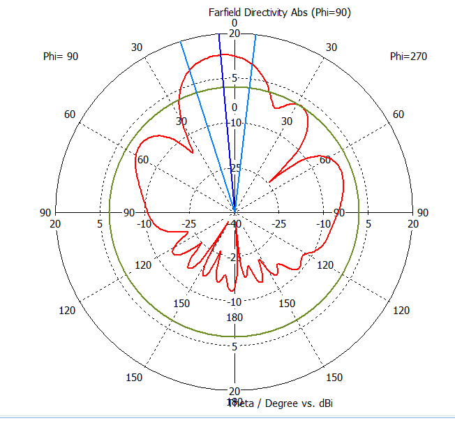
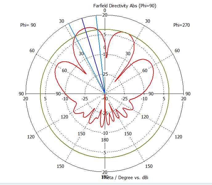
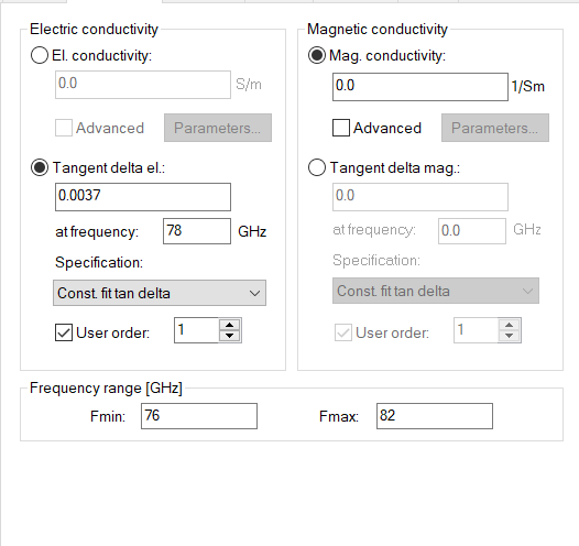
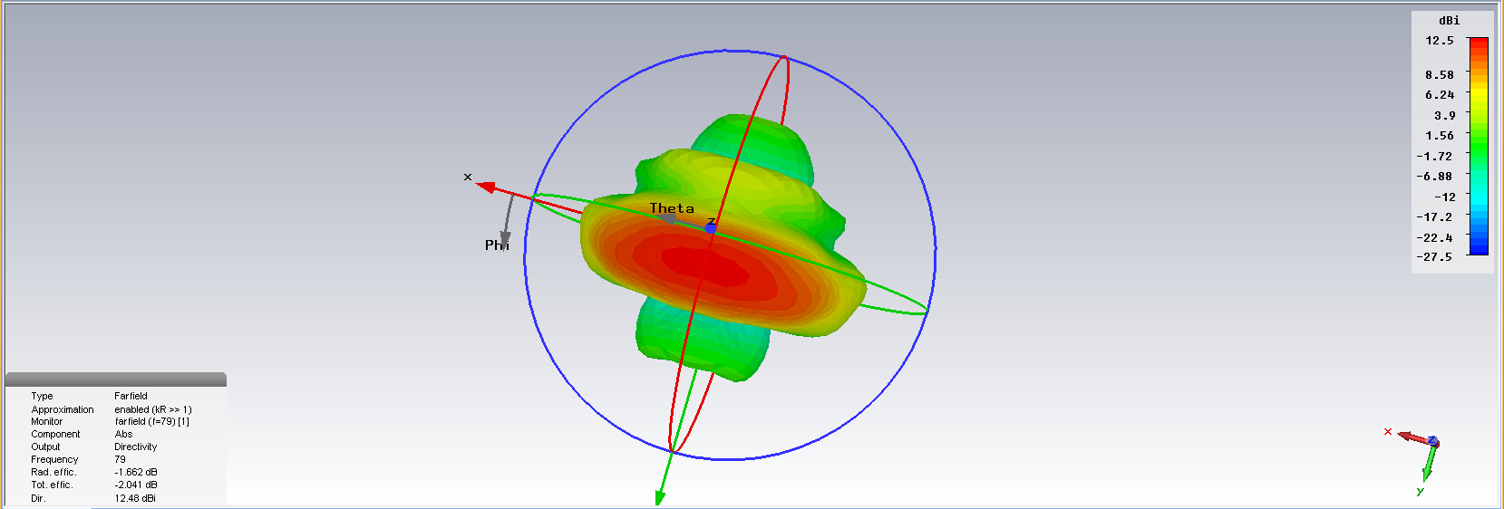
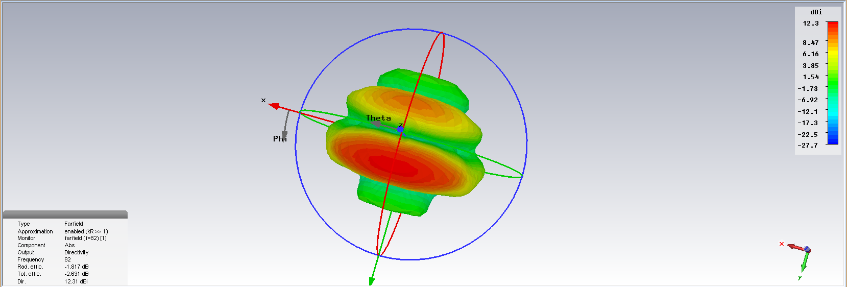
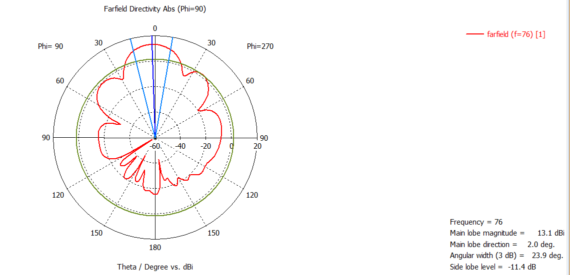
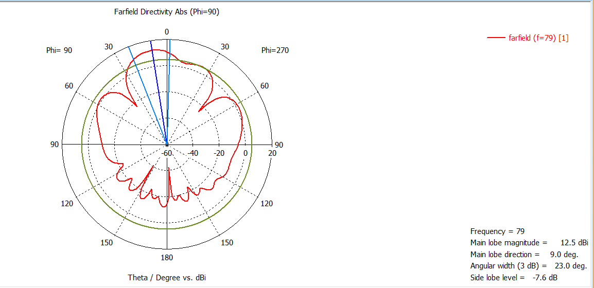
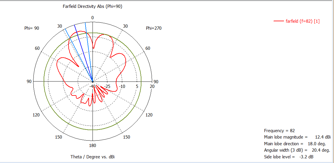
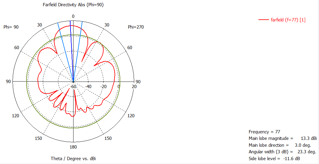
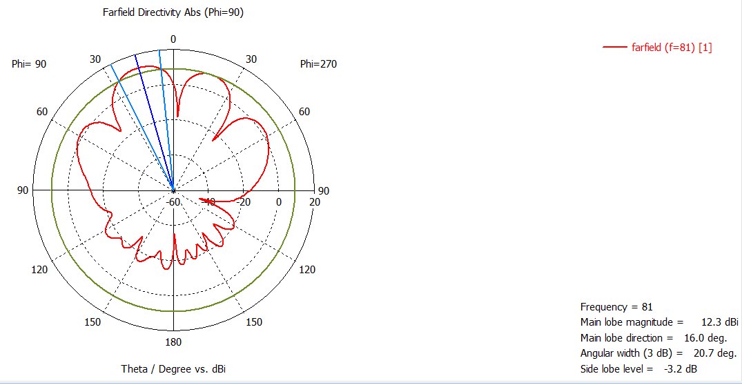
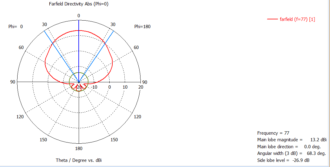
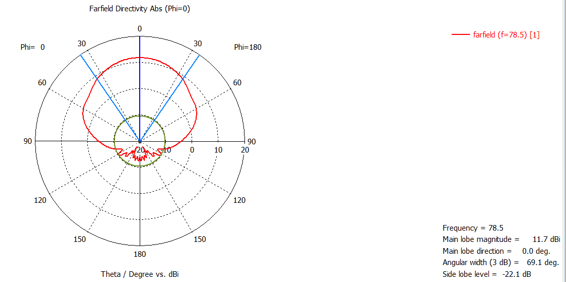
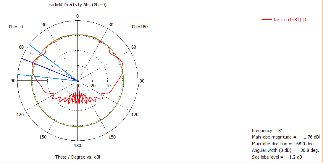
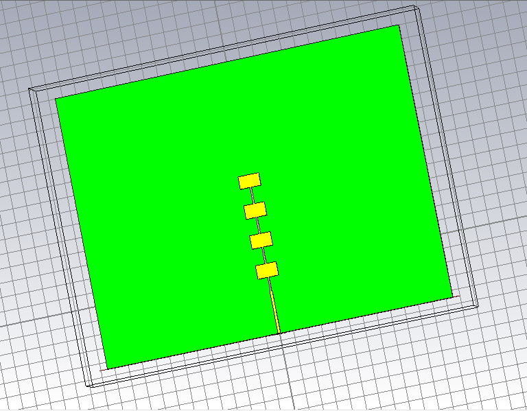
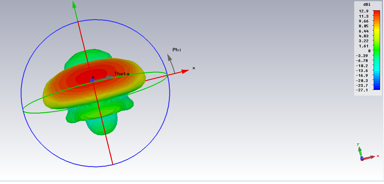
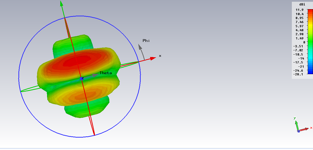
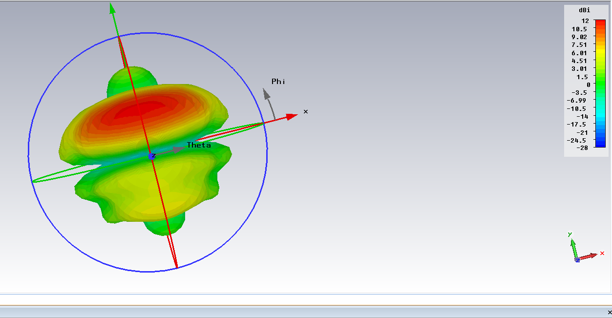
I have simulated an antenna. I have taken the parameters from the Altium design of IWR1642BOOST. I have attached the far-field results at 76, 79, 82 GHz. Kindly confirm if my results are fine or is there anything I should change to get better results. My idea is to include a horn/lens to improve the gain.
Regards,
Prudhvi Sagar
Prudhvi Sagar,
Is this simulation is with Lens or standalone?
Thanks and regards,
CHETHAN KUMAR Y.B.
Hello Chethan,
Yes this is just a standalone patch simulation excited with a waveport. Can you check with any results you have. I want to introduce a lens/horn once I can be confidence upto this point.
Regards,
Prudhvi Sagar
Prudhvi Sagar,
These diagrams are not clear, could you please provide Azimuth plane cut and elevation cuts?
also provide Stackup details, metal thickness, Dk, loss tangent, surface roughness etc.. simulation condition used.
Thanks and regards,
CHETHAN KUMAR Y.B.
Hello Chethan,
I have used the same stack up details as per IWR1642BOOST i.e. top copper 1.6 mil, Substrate thickness 4 mil, Bottom copper 1.2 mil. I have attached some of the results kindly ask me if anything else is required.i am new to CST and also EM theory so kindly bare with me.
Regards,
Prudhvi Sagar
Prudhvi Sagar,
Simulation doesn't look correct, there are signficant slide lobes and nulls at foresight, it is problem.
The Dk value used seem to be incorrect, Dk value changes with the frequency. Rogers, datasheet only provides till 10GHz.
Dk value for the for RO4835LOPRO is 3.44 and Df is 0.0037 at 77GHz .
You could refer to below link calculator for various Rogers materials Dielectric constant dissipation factor values.
https://www.globalcommhost.com/rogers/acs/techsupporthub/en/mwi_calc2019.php
Thanks and regards,
CHETHAN KUMAR Y.B.
Hello Chethan,
Thank you for the support.
I have changed the substrate properties and attached it. I have also attached the results of 3D and polar plot at 76, 79, 82 GHz. Kindly check the results and let me know of any improvements that need to be done. If possible can you also share simulation results which you have for the patch antenna so I can verify?
Regards,
Prudhvi Sagar
Hello,
This shows improvement to your previous results. Please review Azimuth and Elevation cuts together. At 82GHz simulation shows nulls at bore sight, (Also showing tilt of 18 deg) Matching may not be correct at this frequency, It may be good to review S11 plots across frequency. If S11 is bad then you could expect degradation. However this frequency is not supported by TI mmWave sensors.
Using simple Patch array technique it's very challenging to achieve high bandwidth (You are trying to achieve 6GHz),
For the simulation results comparison you could refer http://www.ti.com/lit/ug/swru521b/swru521b.pdf which is done at 78.5GHz.
Thanks and regards,
CHETHAN KUMAR Y.B.
Hello Chethan,
Thank you for the support. I have attached the new results at 77, 78.5 and 81 GHz. I also have attached the S11 plot. I have checked the results you have given. I think my E plane and H plane plots are interchanged compared your results. I also want to simulate a combination of antennas similar to your results where two antennas are coupled, can you suggest me how to achieve that. I am using the combination of TX1 and RX4 as per "High Accuracy Demo".
My main goal through this simulation is to analyze an introduction of lens/horn. Do you suggest if this patch antenna simulation fit enough for that.
Regards,
Prudhvi Sagar
Prudhvi Sagar,
This shows improvement over the previous results. At 81GHz results are not as good as 77GHz.
As antenna contains 4 elements of series patch array, you may have to use the larger radios lens (3-4 inches).
Thanks and regrards,
CHETHAN KUMAR Y.B.
Hello Chethan,
Thank you for the support. I have decided on the shape of the lens from the book you suggested. I will keep in mind to design using a larger aperture lens. How did you arrive at the results where 2 antennas(one TX and one RX) are coupled?
Regards,
Prudhvi Sagar
Prudhvi Sagar
You may want to check with your EDA tool vendor, It's beyond the scope of E2E support.
Thanks and regards,
CHETHAN KUMAR Y.B.