This thread has been locked.

If you have a related question, please click the "Ask a related question" button in the top right corner. The newly created question will be automatically linked to this question.

CCS/IWR1642: Output is fluctuated very fast

Part Number: IWR1642

Tool/software: Code Composer Studio

The output of my application board which is used iwr1642 IC is fluctuating very fast.  I have used gold material in my patch antenna. Is this the reason for the fluctuation in output?  Is there anything i can do from hardware or if possible from the software side to make it steady, responsive and detect object easily? 

  • Hello Arpit Patel,

         It would be difficult to comment on "the output of my application board which is used iwr1642 IC is fluctuating very fast".

    And ENIG surface finish is not recommended as it contains Nickel & Gold alloys, even-though pure gold is good conductor but it needs alloy for stability; Nickel provides better mechanical reliability, But this offers challenge at mmWave frequencies, Nickel offers higher attenuation at mmWave frequency, Hence you could expect higher attenuation on transmitter and receiver paths.

    To understand more "iwr1642 IC is fluctuating very fast", What application you are running? What scene Radar is seeing?  

    Did you compare same with TI EVM under similar environmental conditions? If yes, what are the changes between TI EVM and custom application boards?  

    Thanks and regards,

    CHETHAN KUMAR Y.B.

  • Hi Chethan,

     Thanks for the reply. My application is to switch on the street light when an object is detected for that i am using traffic monitoring code. While separate testing that hardware section. In TI EVM is detection points are zero while facing a wall while in my hardware it is not zero and fluctuation is fast compare to TI EVM. 

    Is it possible to achieve somewhat stability compare to the current output situation of my hardware? Do you or the TI expert team have any solution from the code side? As i am not able to change my hardware now If possible help me from the code and configuration side so that i can make it more stable. Help me with the code side so that i can come out of this issue.

    Is there anything i can do to reduce noise?

  • Hi Chethan,

               Any update?

  • Hello Arpit Patel,

      You could try different Chirp Database and see if you problems.

    http://dev.ti.com/tirex/explore/node?node=ALYHkY2xyhq2-EgWIUuw-Q__VLyFKFf__LATEST

    You may want to try with out of box demo application and compare the results with EVM. 

    Could you post your results comparing with TI EVM.

    Also to understand, if there are any other problems in hardware(than stated above) you need to elaborate changes done from the EVM in schematic and Layout on our custom hardware. 

    Thanks and regards,

    CHETHAN KUMAR Y.B.

  • Hi Chethan,

              I am sending you data of the iwr1642boost and my board for out of box demo. According to visualizer my board only detects humans up to 1 to 2 meters which TI EVM is detecting near about 10 meters. My board hardly shows other objects like bike and other vehicles while the TI EVM has not this issue. Results for traffic monitoring and srr (short range radar) is also the same as out of box demo.

    Could you please tell me how can i use the different chirp database from the link which you have provided?

    We have used RO4350B  material in our 4 layers PCB and immersion gold-(ENIG) in antenna. Here we are using tx,rx and mss pin directly from IWR1642BOOST.

    The schematic and data of boards are attached below.

    Board:

    Board_Sch.PDF

    Data:

    newboard.rtf

    IWR1642BOOST.rtf

  • Hi Chethan,

           Any update?

  • Hi Chethan,

           Any update?

  • Hi Chethan,

          Any update?

  • Arpit Patel,

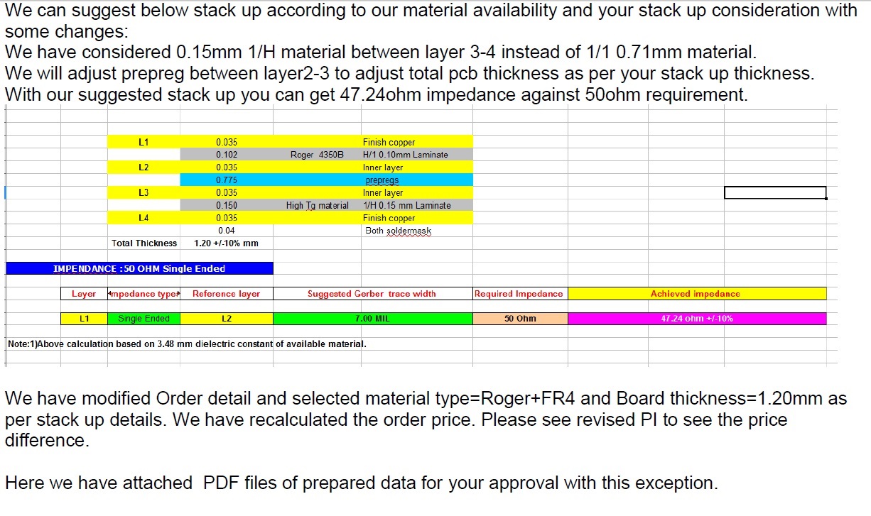
         Could you please show the stackup used in the PCB?  Also could you please share the Layout for review.

    RO4350B stack-up material is different from that of RO4835LOPRO material used in the EVM. 

    Between the regular RO4350B and LOPRO version there is significant insertion loss is present in RO4350B.

    Below graph shows difference between standard laminate vs Lopro laminate. 

    Also I noticed that, there is a fine-print for RO4350B 4mil laminate has different Dk value as compared to RO4835LOPRO version. This may require design update to match the antenna impedance and redesign of transmission lines to meet 50 ohm target. 

    It's better to use Ro4835lopro 4mil substrate as present in the EVM to overcome these challenges, Otherwise design need to be re-centered to DK value of 4350B.

    Thanks and regards,

    CHETHAN KUMAR Y.B.

  • Hi Chethan,

            Stackup 

    Layout:  Layout.zip

    Provide a better solution for this issue.

  • Hello Arpit Patel,

        I see major issue in the Layout, Under the Antenna and Transmission lines there should be ground plane should be present, and no traces are allowed. 

    In the below ground layer under the Antenna and connecting transmission lines, there are traces running under it. 

    Please refer below EVM ground plane for your reference. 

    Please follow EVM layout. 

    Thanks and regards,

    CHETHAN KUMAR Y.B.