This thread has been locked.
If you have a related question, please click the "Ask a related question" button in the top right corner. The newly created question will be automatically linked to this question.
Hello,
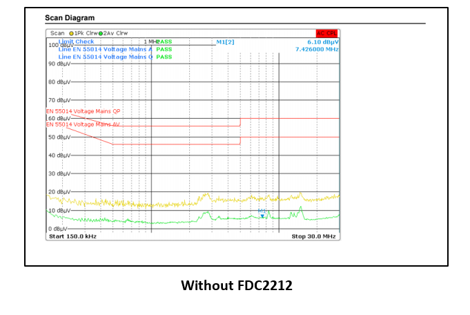
I have a project which includes FDC2212 on it. It fails in Conducted emission test. If i remove FDC2212 from circuit it passes. And it always fails in specific frequencies( 7,43Mhz, 14,86Mhz, and 22,28Mhz). How can i solve this problem? I shared test graphics below.
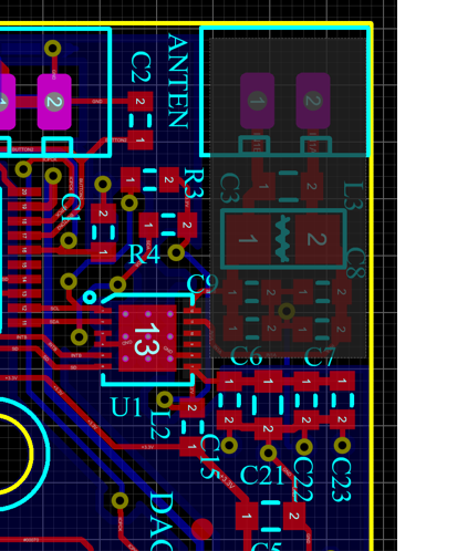
Schematic and layout of my circuit is below.
Enes,
Is 3.72 MHz the resonant frequency of the sensor?
Where are you measuring conducted emissions on your board? Power, GND, signal lines, ANTEN port?
We have an EMI app note for our inductive sensing products. The shielding is not applicable for the FDC devices, but the filtering is:
Resonant frequency of the sensor is about 4 MHz. We measure power lines: L and N. I have read this note before.
As you see in my schematics, i put 18pF's already but not CMC. Now i am designing a new circuit includes CMC. Is there anything that you can suggest ? Do you think if there is a problem with my layout etc?
Enes,
I cannot tell from the picture you sent if there is an issue with the layout. Do you have layer plots that I can look at? In particular, you should look very closely at the grounding scheme of your board.
I suspect that the CMC will help. You could also put a CMC on L and N.