dear
customer is working on a high-quality foot kick project of SAIC-GM automobile Factory based on FDC2212. At present, THE EMC test has found that the radiation exceeds the standard seriously (frequency band below 250MHz), and the modification has been invalid for several times. Please kindly help FAE to support it as soon as possible, and it will be formally tested soon.
The problem is described as follows:
1. IIC speed is 300K, and every 60ms makes FDC chip scan once.The pull-up resistance of 4.7K can be changed to 10K to reduce the radiation, but it still exceeds the standard.
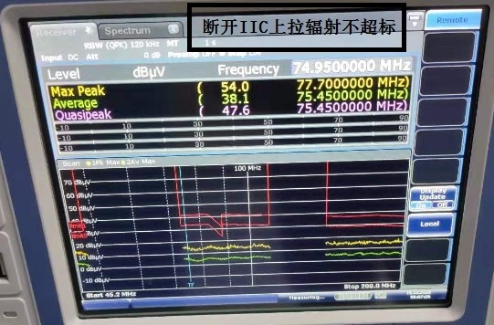
2. Disconnect the IIC pull-up resistance and the radiation drops significantly.Connect IIC pull up resistance, remove the induction antenna, radiation sometimes still exceed the standard.Remove the external crystal vibration, connected with the induction antenna, radiation is still exceeding the standard.
3. No matter the FDC chip uses external or internal crystal oscillator, and the working current is 1.5mA or 0mA, the radiation exceeds the standard.
4. Current tests have found that as long as IIC is in communication, it will lead to serious radiation exceeding the standard.Adding a large common-mode inductance to the right antenna circuit reduces the radiation, but also weakens the antenna signal considerably.
5, FDC chip induction antenna out of the circuit, whether the underlying copper coating has little impact.FDC is through 1 0 Ω resistance and MCU together, multipoint connection and no effect.
The FDC setting parameters are as follows
0x08,0x10,0x89,//89,//RCOUNT_CH0,0x08
0x09,0x10,0x89,//89,//RCOUNT_CH1,0x09
0x10,0x00,0x64,//SETTLECOUNT_CH0,0x10
0x11,0x00,0x64,//SETTLECOUNT_CH1,0x11
0x14,0x20,0x00,//02,//CLOCK_DIVIDERS_CH0,0x14
0x15,0x20,0x00,//CLOCK_DIVIDERS_CH1,0x15
0x19,0x00,0x01,//STATUS_CONFIG,0x19
0x1b,0x82,0x0D,//MUX_CONFIG,0x1B,0x820d
0x1c,0x00,0x00,//RESET_DEV,0x1C
0x1e,0x50,0x00,//DRIVE_CURRENT_CH0,0x1E
0x1f,0x50,0x00,//DRIVE_CURRENT_CH1,0x1F
0x1a,0x36,0x1//INTB enable
any advise? thanks in advance