Other Parts Discussed in Thread: IWR6843ISK
Hi,
I have both IWR6843ISK-ODS and IWR6832ISK and found their antenna layouts are completely different.
The first questions is that how to identify TX1-TX3 antennas on each board. Or is there a convention for all TI radar products?
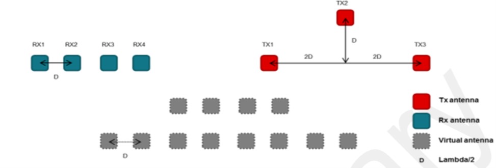
The second one is how the virtual antennas are generated for each board. For the ISK board example, TX antennas are separated in 4xd (d=1/2 lambda) spaces with the middle one upper about 2d spaces, how the vertical antennas are generated? By controlling the phases or something else? Is there more detailed document for the virtual antenna except swra554a?
That really confuses me and it would really appreciated someone could explain that in more details.
Thanks
Tom