Other Parts Discussed in Thread: HDC2080, , TMP108, HDC2010METER-EVM, , HDC2021
- What are the spec differences between the HDC2022 and HDC2080?
- Where is the temperature sensor located on these chips.? We see a window for the RH sensor . Is the temperature sensor also located inside this window or does it sense temperature thru the pins from the PCB.? We want to use this for sensing ambient temperature and humidity.
- Do you have an IC that is similar to TMP108 but with humidity sensor integrated as well? Basically we need a T&H sensor with with a dynamically-programmable limit window, and under- and overtemperature alert functions.
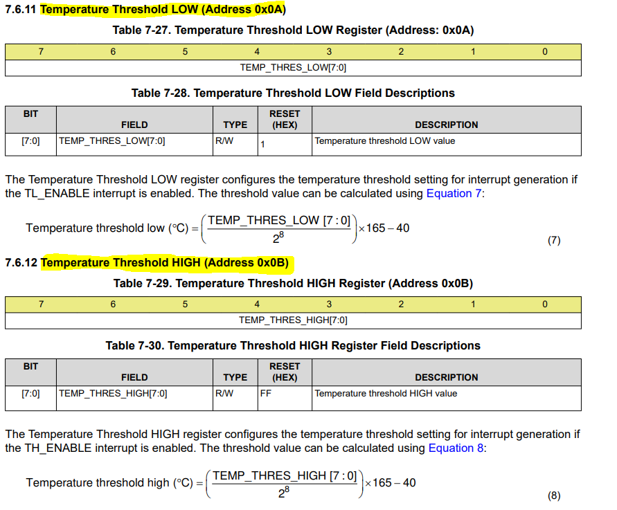
- We want to use the HDC2022 in continuous acquisition mode with interrupts generated when the temperature exceeds the high limit or temperature falls below the low limit. Based on the HDC2022 data sheet , we would have to set register 0x07 to 0xE0 and wait for the interrupt to be generated to wake up our processor. So we should be able to get an interrupt under either of the two condition right? that is either the temp goes below the temp_thr_L or temp goes above the temp_thr_H. Please confirm.
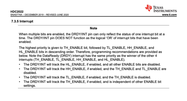
- But your data sheet note on page 12 ( screen shot attached below ) says, the interrupt for low temperature will be generated only if we disable the interrupt for the high temperature. .? We are not clear on what this means. This seems to contradict our assumption #3 above. Can you please clarify.