This thread has been locked.

If you have a related question, please click the "Ask a related question" button in the top right corner. The newly created question will be automatically linked to this question.

TMP235: Temperature drifts reading

Part Number: TMP235

Hi,

I am having a problem with TMP235. I am doing some radiated immunity tests on one of my boards and noticed at frequencies between about 330MHz and 600MHz a temperature drift read by the component from 2 to 3°C.

I initially assumed a drift of the A/D stage, however following further tests, even replacing the sensor with a resistive divider, it seems that the problem is a drift of the component itself at these frequencies. I provided a power supply bypass at the input with two 100nF // 100pF capacitors, at the output we have a 100pF capacitor directed between Vout and GND, then an R-C filter as suggested in the datasheet positioned near the A / D. In the position where the TMP235 is mounted it is not possible to have a homogeneous diffuse ground plane as we are close to the cold junction of a thermocouple, however below the component there is a zero volt plane.

Do you have any indications or application notes more specific than the datasheet dedicated to how to make this specific type of component more immune? Thanks,

Antonio

  • Hi Antonio,

    I must apologize; I don't have further information specific to TMP235 and radiated testing. 

    thanks,

    ren

  • Antonio,

    This part has a constant current sink and uses a special PN junction to measure the temperature. It can be possible for EMI to interfere with our sensor, but the level of EMI would have to be very high. The most likely cause would be common mode electromagnetic interference and the EMI would be coupled into the traces on the PCB. The end result would be rectified current in the TMP235 part, but that would not be the fault of the TMP235.

    This sounds like a layout issue. Having a ground plane with a controlled impedance on any PCB that is being tested for susceptibility is very important. If the traces are run in such a way as they do not have a solid ground plane or there is a slotted ground plane then it is possible that the EMI is showing up as an increase in current and changing the analog voltage coming from the TMP235

    We can go into more detail on this if you would like. My first guess would be to look at the traces from the controller to the sensor, and verify that they have a good ground plane under them.

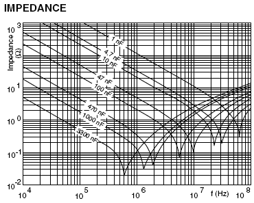
    The chart below is only a basic impedance plot. Look at the impedance plot for your specific capacitors. The frequencies you pointed out suggest a 2.2nf capacitor would benefit you on the input and output of the sensor. The length of the traces could also be a fraction of a wavelength that can also make them more sensitive.

    I would also suggest using ferrite beads on the output and the input to the ADC. Just more suggestions. 

    Let me know if I can help further.