Hi,
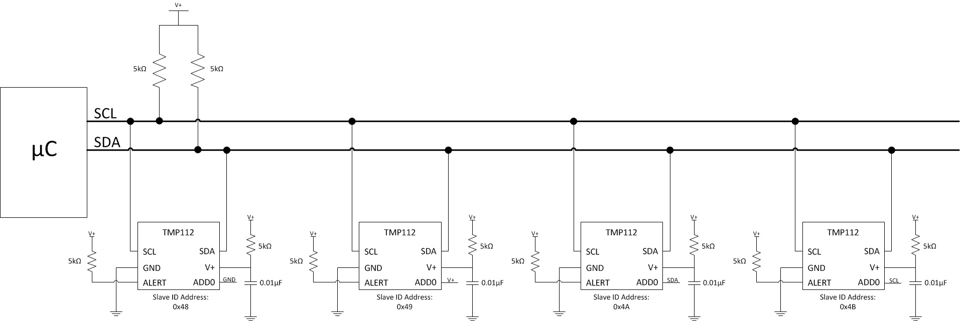
I have connected in the following way (please refer to the attachment) is it correct? Please assist me in interfacing these 4 devices to a single bus.
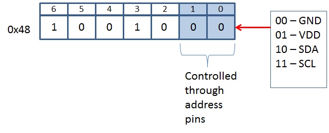
1. How ADD0 pin works when 4 devices are connected onto single bus, how ADD0 pin differentiates SCL and SDA lines when it is connected to them?
2. Is there any dimension constraints for resistor and capacitor used in the schematic?
Regards