This thread has been locked.

If you have a related question, please click the "Ask a related question" button in the top right corner. The newly created question will be automatically linked to this question.

CCS/IWR1642BOOST: IWR1642BOOST program parameters are configured after running, prompting configuration error

Part Number: IWR1642BOOST

Tool/software: Code Composer Studio

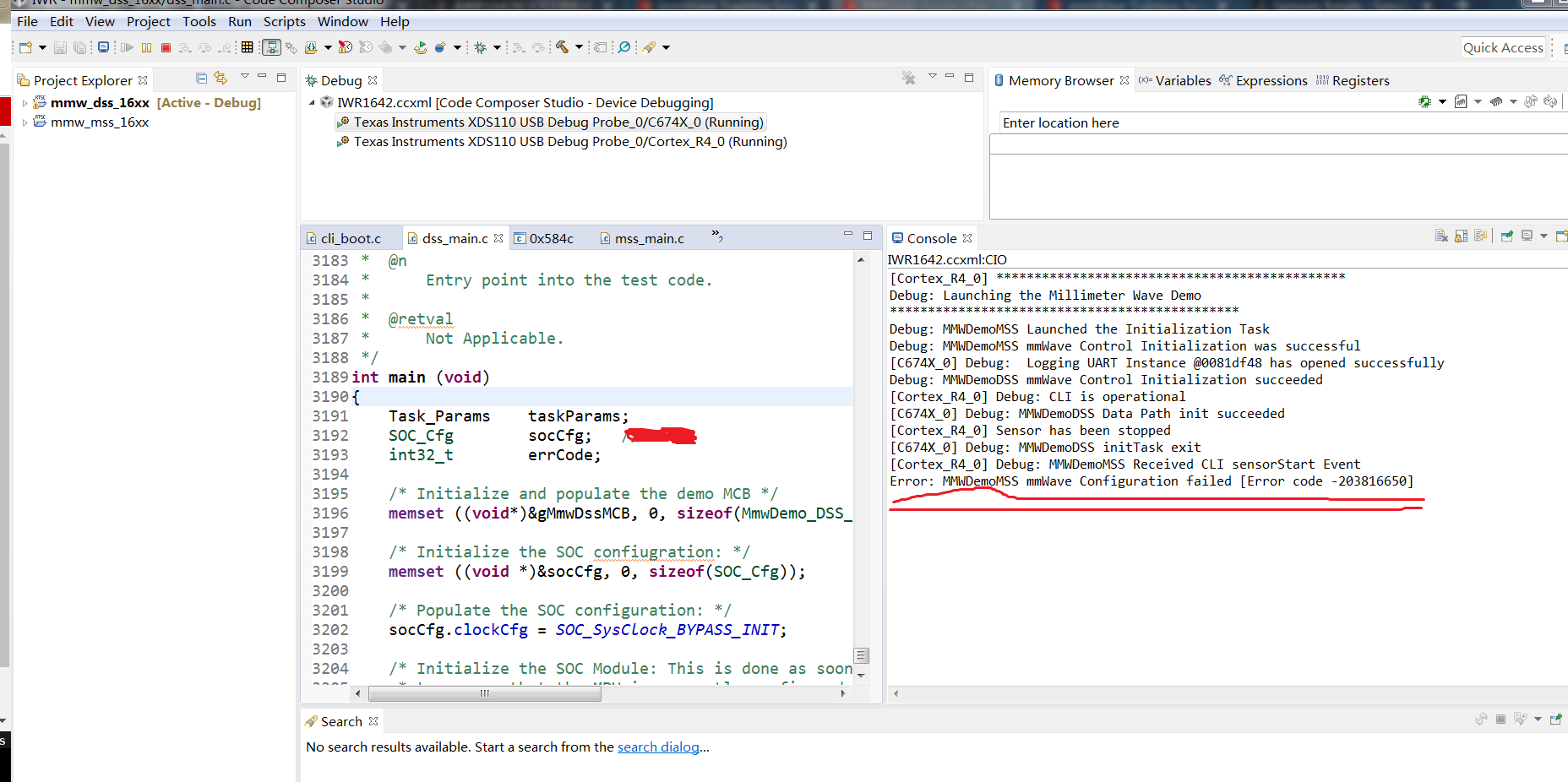
I now have an IWR1642BOOST DEMO on hand. I can modify the program to make the board run independently from the host computer. The parameters can be manually configured. Now the program parameters are configured according to my needs. The configuration parameters are incorrect after running, as shown in the figure. Failed, but how can I check which parameter configuration failed? If I don't know which parameter is configured incorrectly, I can't make the corresponding modification, which is very unreasonable. Thank you

  • Hello,

    Can you please provide your chirp configuration?

    Regards
    -Nitin
  • Hi Nitin,
    This is the parameter I set, 128 sample points, 512 chirp, how many chirp can I set up? I set 128 points, 256 chirp, but the program will report an error. It seems that up to 128 chirp can be set. Is this the case? But I don't see the upper limit of chirp in the data.


    "profileCfg 0 76 81 7 30.96 0 0 3.9 1 128 6250 0 0 30",
    "chirpCfg 0 0 0 0 0 0 0 1",
    "chirpCfg 1 1 0 0 0 0 0 0",
    "frameCfg 0 3 128 0 25.48 1 0",


    Regards
    -ZHG
  • Hello,

    There are a few errors in your configurations as noted below:

    1. "chirpCfg 0 0 0 0 0 0 0 1",
        "chirpCfg 1 1 0 0 0 0 0 0", -> (Invalid chirp configuration: The last value is the TX Channel bitmask which determines which TX channel wil be used to transmit this chirp.)

    2. "frameCfg 0 3 128 0 25.48 1 0", -> (Invalid frame config:  You have specified Chirp Start Index from 0 to 3 i.e. you want to transmit use 4 chirps, looping over 128 times, but you have created only two chirps above, chirp index 0 and chirp index 1.

    To fix the above errors:

    1. Change the second chirp config to "chirpCfg 1 1 0 0 0 0 0 2", (i.e. use TX2) and

    2. Change the frameCfg to "frameCfg 0 1 128 0 25.48 1 0" (i.e. loop over chirp indices 0 and 1)

    I would highly recommend you to read the mmWave SDK user guide, section Configuration File Format section and also look at the example configuration files provided in the demo directory under C:\ti\mmwave_sdk_02_01_00_04\packages\ti\demo\xwr16xx\mmw\profiles to understand the relationship between the various parameters.

    Thanks

    -Nitin


  • Hi,Nitin
    Thank you very much for your help. Your reply has helped me a lot, but I still have a few questions to ask.

    1、Why is this place setting two chirpCfg? What is their role?

    chirpCfg 0 0 0 0 0 0 0 1
    “chirpCfg 1 1 0 0 0 0 0 0 ”

    2、The configuration you mentioned above should be two antennas transmitting four antennas for reception. I want to set up an antenna to send four antennas to receive, the sampling point is 128, 256 chirp, but obviously I failed, the program still shows configuration failure after running, as I mentioned before. May I ask if there is any problem with this configuration?

    "profileCfg 0 76 177 7 18.24 0 0 54.825 1 128 6250 0 0 30",
    "chirpCfg 0 0 0 0 0 0 0 1",
    "chirpCfg 1 1 0 0 0 0 0 1",
    "frameCfg 0 1 128 0 100 1 0",

    3、I found the documentation you mentioned in this path, but I can't see any relationship between these parameters.

    Can you explain it specifically?

    Thanks

    --ZHG

  • Hello,

    You've not provided the error value but looking at the profileCfg command, I see that you are exceeding 1GHz of RF bandwidth (Ramp end time x Frequency Slope comes out to 1000.008 GHz). For 76GHz start frequency, the RF bandwidth is limited to 1GHz and exceeding this bandwidth will cause an error. You can either reduce the frequency slope or change the start frequency to 77Ghz (in which case the RF bandwidth is limited to 4GHz)

    Please also look at the following thread which provides help on decoding mmwavelink errors:

    https://e2e.ti.com/support/sensors/f/1023/t/772813

    To develop a fundamental understanding of the chirp configuration, please look at the following video from the mmWave Training Series. You should be able to understand the organization of the Chirp and profile RAMs in device memory and how they are programmed. It is essential that you understand the concepts described in this video and understand the configurations commands described in the Configuration file format section of the MMWAVE SDK user guide.

    mmWave Radar Programming Model

    Thanks

    -Nitin