


Other Parts Discussed in Thread: BOOSTXL-PGA460, , MSP-EXP430F5529LP, PGA460
Hi,
I am trying to build UART communication between a MCU board ( Infineon XC2267M) to BOOSTXL-PGA460 (PGA460-Q1 Ultrasonic Sensor Signal Conditioning EVM With Transducers).
================= the good sample from original EVM ==============================
the PGA460-Q1 EVM GUI is able to connect to MSP-EXP430F5529LP + BOOSTXL-PGA460 motherboard + BOOSTXL-PGA460 daughtercard, and Transducer echo data dump command run successfully.
here is the observation and scope screen during UART communication
J1 pin 4 (UATX) measured 3.83V
J1 pin 1 (3v3) measured 3.9V
J1 pin 21 (5V) measured 5.37V

UART baud rate 192 kbps
================= the failed sample from XC2267M board ==============================
As slau659b EVM guide instructed, BOOSTXL-PGA460 motherboard was modified as below.
a) power-mode-selector jumper block (J7), Pin3-4 Shorted
b) 12V applied to BOOSTXL-PGA460's J6 pin PWR
c) 3.3V applied to BOOSTXL-PGA460's J1 pin 1 (3v3)
d) J1 pin 22 (GND) wired to XC2267M MCU board
e) XC2267M MCU P1.2 (U2C1 RXD) fly wired to BOOSTXL-PGA460 J1 pin 3 (UARX )
f) XC2267M MCU P1.1 (U2C1 TXD) fly wired to BOOSTXL-PGA460 J1 pin 4 (UATX )
g) XC2267M MCU UART baudrate set to 57.6 kbps
h) XC2267M MCU UART Tx 0x55 0x09 0x4C 0xAA (Register read) which copied from EVM good sample
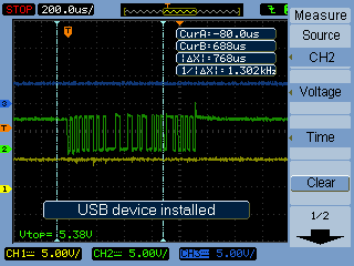
and here is the observation and scope screen,
J1 pin 1 (3v3) measured 3.6V
J1 pin 4 (UATX) measured 5.38V, why good sample show 3.3v level?
J1 pin 3 (UARX) measured 5.31V, but not PGA460 response at all, why good sample show 0v level?
the EVM still works after restore the modification, Can someone check what I missed in my own config?
Thanks a lot
| P1.2 | U2C1 RXD |


