This thread has been locked.

If you have a related question, please click the "Ask a related question" button in the top right corner. The newly created question will be automatically linked to this question.

PGA300EVM-034: Excessive current in current mode

Part Number: PGA300EVM-034

Hello,

I evaluate PGA300 in current mode with PGA300EVM-034.

a jumper is set in current mode and power is applied to PGA300, the current that should be less than 4 mA flows about 19 mA.

What do you think is the reason?

The sensor uses our company's one, and I confirmed that the ADC was changed by applying pressure when setting the sensor gain.

When the DAC was output from the GUI, the output current changed up to around 35mA.

I think the current consumption of the board is a problem, but what about?

Regards

  • Hello,

    Can you please show a picture of your jumper settings? And can you also share the specifications of the sensor you are using? Has the PGA300 already been calibrated using this sensor? Can you also share a dump of the EEPROM contents of your PGA300 device?

    To check the PGA300 operation on its own, the first step will be to place the PGA300 in reset mode using the GUI. You can go to the DAC settings page and test the DAC output by directly entering in specific DAC codes. If the current loop output is still very large when you have a small code set, then there could be some other problem with the analog EEPROM settings.

    Regards,

  • Hello Scott,

    I show my jumper setting in the picture.

    And my sensor specification is shown below.

    ・Rated pressure:0 - 200 kPa

    ・Offset voltage:1.25 mV/V

    ・Span voltage:4.90 mV/V

    ・bridge resistance:Ave. 3.515 kΩ

    This sensor has not been calibrated yet.

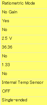
    EEPROM config-Analog is set as shown in the picture.

    P gain was calculated using the GUI function.

    When I use 'Guided Calibration' and tested the DAC output by directly entering in specific DAC codes, 766 is about 19mA and 2700 is about 35mA.

    From this result, I thought that the basic current consumption might be large.

    Regards,

  • Hello,

    The jumper configuration and the EEPROM analog settings look like they should not be causing any problems.

    Where are you measuring the current? I recommend removing the J12 shunt, and placing your ammeter leads on each of the two pins for J12. This will measure only the current in the 4-20mA loop that is controlled by the PGA300.

    Regards,

  • Hello Scott,

    An ammeter is connected to DC24V power supply in series.

    I can't confirm this week, but I'll try to measure the current next week by the method you taught me.

    Regards,

  • Hello,

    Your current measurement setup will most likely be causing the results you see. There is a large amount of supporting circuitry on the EVM that draws power (usually about 14-17mA on its own) that is added to the PGA300's loop current when you measure the power going to the entire EVM. Please let me know if you still have an incorrect output after measuring just the current in the PGA300 current loop.

    Regards,

  • Hello Scott,

    After wiring according to your settings, I was able to confirm that the initial current is about 3mA.

    In addition, when 3 patterns of DAC (766,1800,2700) were input with the GUI function, it was confirmed to be about 4-20 mA.

    Probably as you said, the current of the EVM support circuit was added.

    Our products measure by connecting an ammeter in series with the power supply.

    When creating a circuit/board at our company, is there a problem in creating the circuit without considering the additional current due to the EVM support circuit like this time?

    Should we consider the current consumption of the circuit we made?

    Thanks for your kind advice.

  • Hello,

    You are welcome to share your schematic if you have any concerns. The PGA300 normal operation current is in the 2-3mA range, so as long as any external components do not draw enough to push the total over 4mA, the PGA300 will be able to regulate the current in the 4-20mA range without any problems. You can see an example circuit here: https://www.ti.com/tool/TIDA-00788

    Regards,

  • Hello Sccot,

    Thank you for advice. I will refer to it.

    Regards,