This thread has been locked.

If you have a related question, please click the "Ask a related question" button in the top right corner. The newly created question will be automatically linked to this question.

IWR1843: What conditions will BSS response message id(rl_rxMsg.hdr.opcode.b10MsgId) of 0(RL_RF_RESP_ERROR_MSG)?

Part Number: IWR1843
Other Parts Discussed in Thread: IWR6843, AWR1843BOOST, AWR1843,

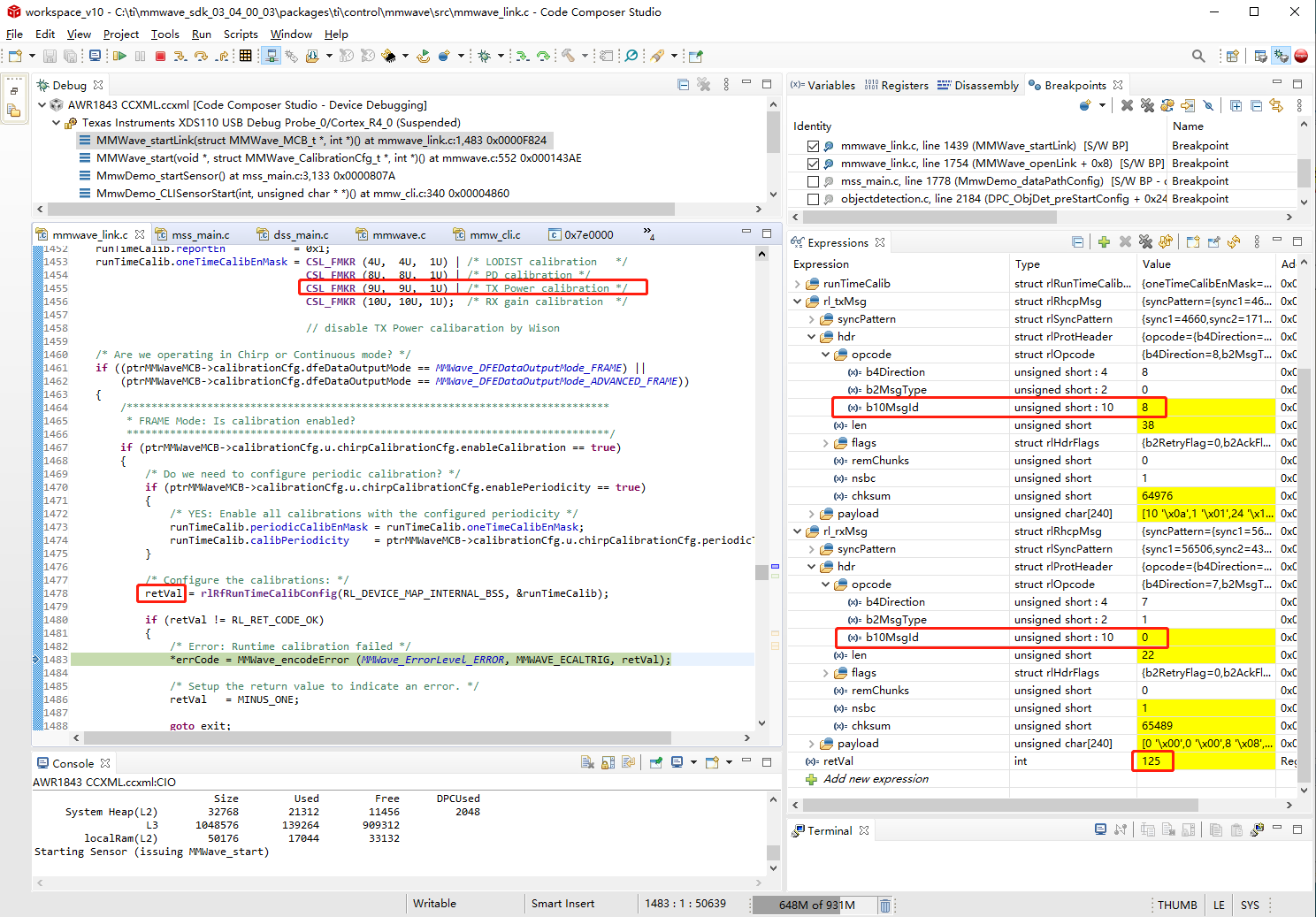
After rlRfRunTimeCalibConfig is called, including the configuration of the TX power calibration enable, BSS responses message id(rl_rxMsg.hdr.opcode.b10MsgId) of 0 but the message id(rl_txMsg.hdr.opcode.b10MsgId) sending by MSS is 8. So, why the device receives the msg-ID '0' from BSS after TX power calibration enable in RF periodic calibration, and what conditions will BSS response message id of 0?

SDK version: 3.4.0.3

Device: custom harware on IWR1843

Related issue: https://e2e.ti.com/support/sensors/f/1023/p/937708/3466458#3466458

  • Hello

    Are you trying to enable Monitors on IWR6843 device.

    You may want to try this on AWR1843 device to make sure they are working fine - do you have access to an AWR1843boost board.

    Thank you,

    Vaibhav

  • Hi Vaibhav,

    I use mmWave link unit test to enable monitors on IWR1843, but rlRfDigMonEnableConfig API returns 250, which indicates device type is not ASILB. Monitors can be enable on AWR1843BOOST board.

    TX power calibration enable fails on IWR1843. What are the reasons for this failure?

    Thanks and regards,

    Wison

  • Wison,

       IWR1843 supports only below monitors, For more details, please refer to the data sheet.

    If you want more comprehensive monitors you may have to refer to AWR1843 device.


    Before running the run time calibration, you need to ensure RF_init need to be performed and you should not see any calibration errors. Then only you could proceed for run time calibrations. If RF init fails we need to identify which calibration has failed based on the error code/response and address those issues. 

    Thanks and regards,

    CHETHAN KUMAR Y.B.

  • Hi CHETHAN KUMAR Y.B.,

    RF init calibration configuration returns 0 before rlRfInit is called and RF init return 0. The debug info is as shown below.

    And then enable TX Power calibration and configure RF run time calibration but it returns 125. The debug info is as shown below. The message id from BSS response header is 0.

    Thanks and regards,

    Wison

  • Hello Wison,

    Can you please let us know if you've enabled TX power calibrations in the RFINIT calibration configuration API? 

    The return value of RFINIT API doesn't indicate the status of the individual calibrations. That data is present in the ASYNC event report (RL_RF_AE_INITCALIBSTATUS_SB) that is sent by the device after the RFINIT calibrations are complete. Can you please check if the status of the TX POWER calibration is in PASS state?

    Regards,

    John.

  • Hi John,

    Yes. All calibrations have been enable before rlRfInit in MMWave_openLink function. The API rlRfInitCalibConfig returns 0.

    But in the RL_RF_AE_INITCALIBSTATUS_SB event report, the result of calibStatus is 0xdfe that indicates TX power calibration FAILURE.

    So, it's because the failure of TX power calibration in the RFINIT calibration that rlRfRunTimeCalibConfig returns error code 125. What factors are related to failure of TX power calibration init?

    Thanks and regards,

    Wison

  • Wilson,

    You are right. We may have to identify failure of Tx power calibrations.

    Are you running this on TI IWR1843BOOST EVM or custom hardware? If it's on custom hardware you may have to identify difference between the two hardware. 

    Thanks and regards,

    CHETHAN KUMAR Y.B.

  • Hello CHETHAN KUMAR Y.B.,

    Thank you. I want to know the reasons for failure of TX power calibrations init.

    It runs normally on AWR1843BOOST EVM board but it fails to run on custom IWR1843 hardware. The antennas are different between them. I don't have IWR1843BOOST board to test.

    Thanks and regards,

    Wison

  • Wison,

         There could be various reasons, We need to identify the differences between AWR1843BOOST EVM and 1843 custom hardware. Could you post your schematic/Layout of the hardware?

    For example, it could be due to power supply configuration change, OR due to problem in the Layout from the Power delivery network providing the insufficient transient current during the Power amplifier calibrations, or Antennas may not be matched correctly for the PA output ports etc. 

    You could review below schematic/Layout/Bring up checklist to identify the differences between the two designs.

    https://www.ti.com/lit/zip/spracl2 

    Thanks and regards,

    CHETHAN KUMAR Y.B.

  • CHETHAN KUMAR Y.B.,

        Thank you very much. We will review the layout guidelines first.

    Thanks and regards,

    Wison

  • Wison,

         Thanks for your acknowledgement. 

    Thanks and regards,

    CHETHAN KUMAR Y.B.