This thread has been locked.

If you have a related question, please click the "Ask a related question" button in the top right corner. The newly created question will be automatically linked to this question.

PGA300: How convert PGA300 GUI voltage value to AD value of PGA300 EEPROM

Part Number: PGA300

Hello,

I don't know how calculate AD value of PGA300 EEPROM from PGA300 GUI voltage value. I would like to write AD value to PGA300 EEPROM by OWI communication that I prepared instead of GUI. The following are the items I want to attempt, and the attached file is a example.

・Normal Pressure upper value

・Normal Pressure lower value

・Clamp Vlue -lower

・Fault configurable value

example.xlsx

  • Hello,

    The values that you are referring to are all related to the DAC output, and not the ADC. The value stored in the EEPROM register directly correlates to the desired DAC code for each of those settings. Since the DAC is 14 bits, and these values are stored in two 8 bit registers, the first 2 bits of the MSB registers are not used. This is described in the updated PGA300 datasheet that is currently available on the PGA300 product page.

    Regards,

  • Hello,

    I clearly understand the place where AD value should be written. However, I don't know the calculation method how to convert voltage value to AD value yet. An example I've uploaded as an Excel file is converted voltage value to AD value like followings.


                     GUI(Voltage)   EEPROM(AD)
    ・Normal Pressure lower value    0.25V               →   0x327
    ・Normal Pressure upper value   3.5V               →   0x2C8D 
    ・Clamp Vlue -lower                       0.2V               →   0x284
    ・Clamp Vlue -Upper                      3.5V               →   0x2D30
    ・Fault configurable value              3.75V                →   0x2FBC

    Could you tell me calculation method of AD value from volotage? For example, how to get 0x327 from 0.25V (Normal Pressure lower value). Are there any formula to convert voltage to AD?

    Regards,

  • Hello,

    The value in the EEPROM is the code that is written to the DAC. The voltage the DAC produces depends on the DAC gain setting and whether it is in absolute or ratiometeric mode. 

    In absolute mode, the DAC reference is 1.25V, so the LSB size is 1.25V/ 2^14 or about 76uV. The gain stage can be configured for 2, 4, 6.67, or 10V/V. The output voltage = (DAC code) * (LSB size) * Gain.

    Regards,

  • Hello,

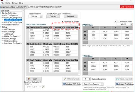
    Thank you for teaching. I'm currently using absolute mode. Could I request you additional question? I concern about a difference. After compensation calculation using by GUI between Desired_V and CalcDAC, the following AD values read from EEPROM are slightly difference that I compared with Write Data.

    ・Normal Pressure upper value

    ・Normal Pressure lower value

    ・Clamp Vlue -lower

    ・Clamp Vlue -Upper

    ・Fault configurable valuu

    I expect that diffrence comes from bit resolution or the difference between the value calculated from compensation equation and actual value. If it possible, could you tell me the algorithm of compensation formula?

    Regards,

  • Hello,

    The specific algorithm for calculating the ADC and DAC compensation is proprietary to TI, but I can explain it in a general sense. The desired voltage and the original DAC code (far left) are used to set your desired curve, and by entering the measured voltage you the actual DAC code needed to match the desired voltage can be calculated through polynomial curve fitting.

    Regards,