This thread has been locked.

If you have a related question, please click the "Ask a related question" button in the top right corner. The newly created question will be automatically linked to this question.

some configuration crash

Part Number: MMWCAS-RF-EVM
Other Parts Discussed in Thread: AWR2243, AWR1243

Hello i am trying to find the best configuration for our needs, but i don't know why some configuration doesn't work even if mmwave studio doesn't give us an error.

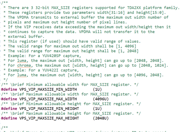
I am trying configurations with sampling rates from 4Mbps to 22,5 Mbps and slope from 22 Mhz/us to 250 Mhz/us, using the maximum IF bandwidth (4GHz).

But some configurations crash.

Iam trying those configurations using mmwave studio lua cascading scripts.

For exemple 4000kbps sampling 22Mhz/us 687 samples idle time 31us and adc start time to 5 us configuration doesn't work

I am using tdm mimo with 12Tx and 16Rx and complex samples

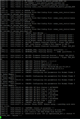
This configuration seems valid for mmwave studio but when executing cascade_capture script TDA fail to arm

did someone know why some configurations doesn't work even if in theory everything seems fine

Regards,

Vincent

  • Hi,

    Sorry for the delay.

    Will be able to get back to you before Monday

    thank you

    Cesar

  • Hi,

    Could you provide your script, we will try to replicate the issue at our end.?

    Ideally you need to provide sufficient time for ADC data transfer from AWR2243/AWR1243 over CSI to TDA and then TDA to SSD storage, before next frame/chirp data gets generated. This depends on ADC idle time, ADC sampling rate, CSI transfer rate etc.

    Please consider for proper calculation on that first.

    Regards,

    Jitendra

  • Hi,

    thanks for your answer. You will find my lua script linked with this message.

    I checked my config. Acquisition time, sampling etc. seems okay

    thx,

    Vincent

    Cascade_Configuration_MIMO.rar

  • Hi Vincent,

    Please provide me two days to check on this. I'll get back on this by Monday.

    Regards,

    Jitendra

  • Hi Jitendra,

    did you check my config which was failing ?

    thanks,

    Vincent

  • Hello Vincent,

    Sorry I don't get access to remote cascade setup.

    Meanwhile could you look at this FAQ page if that resolves your issue.

    https://e2e.ti.com/support/sensors/f/1023/t/925288

     And make sure that you use right firmware or patch version for your AWR2243, if that ES1.0 (DFP 2.1.5.3) or ES1.1 (DFP 2.2.2.1)

    Regards,

    Jitendra

  • Hello,

    You need to increase the chirp idle time to ~40usec

    Size of each chirp can be calculated by the formula mentioned in this FAQ (https://e2e.ti.com/support/sensors/f/1023/t/856054 

    chirp data size = (1481*2*2*4) = 23696

    Time to transfer (during Idle time) = 23696/600mbps (CSI speed) = ~40usec 

    change in LUA script->   local idle_time                 =   40 ----31      -- us

    I tried to change idle time to 40usec and I am able to configure and capture the data.

    Regards,

    Jitendra

  • Hello,

    Thanks for your answer. In fact the idle time was the issue for this config i changed it and now this config workes perfectly.

    But we are still facing issues with RF configuration.

    Please find attached the failed config file for sdk. (sampling_rate=4000kHz, numAdcSamples = 687, adcStart = 5µs, idle = 20µs, rampEndTime = 181 µs, slope= 22 Mz/µs)

    This config fail with this message on Serial interface

    Thx in advance for your support,

    Vincent

    5355.cascade_fe_params_mimo_master.txt
    # Any line that starts with a # is treated as a comment and ignored
    # Please do not start any non-blank line with a space
    # Please do not use hexa decimal values
    
    # NOTE: ADC Data NON-INTERLEAVED and 16-BIT
    
    version                     4
    
    ###### lvdsClkCfgArgs ######
    # 0 - SDR Clock
    # 1 - DDR Clock (Only valid value for CSI2)
    laneClkCfg                  1
    
    # 0000b - 900 Mbps (DDR only)
    # 0001b - 600 Mbps (DDR only)
    # 0010b - 450 Mbps (SDR, DDR)
    # 0011b - 400 Mbps (DDR only)
    # 0100b - 300 Mbps (SDR, DDR)
    # 0101b - 225 Mbps (DDR only)
    # 0110b - 150 Mbps (SDR, DDR)
    dataRate                    1
    
    ###### hsiClkCfgArgs ######
    # High Speed Interface Clock configurations
    # SDR - 0x5(900 mbps), 0xA(600 mbps), 0x6(450 mbps),
    #       0x2(400 mbps), 0xB(300 mbps), 0x7(225 mbps)
    # DDR - 0xD(900 mbps), 0x9(600 mbps), 0x5(450 mbps),
    #       0x1(400 mbps), 0xA(300 mbps), 0x6(225 mbps),
    #       0xB(150 mbps)
    hsiClk                      9
    
    # Total Number of chirp profile configurations
    # The profileCfgProfileId should be in the contiguous range [0..(numProfileCfg-1)]
    numProfileCfg               1
    
    ###### BEGIN profileCfgArgs [0] ######
    profileCfgProfileId         0
    
    # Allowed values for "hpfCornerFreq1"
    # RL_RX_HPF1_175_KHz     = 0
    # RL_RX_HPF1_235_KHz     = 1
    # RL_RX_HPF1_350_KHz     = 2
    # RL_RX_HPF1_700_KHz     = 3
    hpfCornerFreq1              RL_RX_HPF1_175_KHz
    
    # Allowed values for "hpfCornerFreq2"
    # RL_RX_HPF2_350_KHz     = 0
    # RL_RX_HPF2_700_KHz     = 1
    # RL_RX_HPF2_1p4_MHz     = 2
    # RL_RX_HPF2_2p8_MHz     = 3
    # RL_RX_HPF2_5p0_MHz     = 4
    # RL_RX_HPF2_7p5_MHz     = 5
    # RL_RX_HPF2_10_MHz      = 6
    # RL_RX_HPF2_15_MHz      = 7
    hpfCornerFreq2              RL_RX_HPF2_350_KHz
    
    rxGain                      30
    digOutSampleRate            4000
    numAdcSamples               687
    adcStartTimeUSec            5
    idleTimeUSec                20
    rampEndTimeUSec             181
    startFreqGhz                77
    txOutPowerBackoffCode       0
    txPhaseShifter              0
    freqSlopeConstMhzPerUSec    22
    txStartTimeUSec             0
    ###### END profileCfgArgs [0] ######
    
    # Transmit Antenna Mask
    # 1 - TX1
    # 3 - TX1 + TX2
    # 5 - TX1 + TX3
    # 7 - TX1 + TX3 + TX2
    txAntEnableMask             7
    
    # Receive Antenna Mask
    rxAntEnableMask             15
    
    # Total Number of chirp configurations
    # The chirpCfgArgsID should be in the contiguous range [0..(numChirpCfg-1)]
    # The pairs [chirpStartIdx, chirpEndIdx] across the profiles should be contiguous
    numChirpCfg                 9
    
    # Cascade - TX1, TX3 - AZIMUTH TX2 - ELEVATION
    ###### chirpCfgArgs ######
    chirpCfgArgsID              0
    chirpCfgProfileId           0
    chirpStartIdx               0
    chirpEndIdx                 0
    adcStartTimeVarUSec         0
    idleTimeVarUSec             0
    txEnable                    0
    startFreqVarHz              0
    freqSlopeVarHz              0
    
    ###### chirpCfgArgs ######
    chirpCfgArgsID              1
    chirpCfgProfileId           0
    chirpStartIdx               1
    chirpEndIdx                 1
    adcStartTimeVarUSec         0
    idleTimeVarUSec             0
    txEnable                    0
    startFreqVarHz              0
    freqSlopeVarHz              0
    
    ###### chirpCfgArgs ######
    chirpCfgArgsID              2
    chirpCfgProfileId           0
    chirpStartIdx               2
    chirpEndIdx                 2
    adcStartTimeVarUSec         0
    idleTimeVarUSec             0
    txEnable                    0
    startFreqVarHz              0
    freqSlopeVarHz              0
    
    ###### chirpCfgArgs ######
    chirpCfgArgsID              3
    chirpCfgProfileId           0
    chirpStartIdx               3
    chirpEndIdx                 3
    adcStartTimeVarUSec         0
    idleTimeVarUSec             0
    txEnable                    0
    startFreqVarHz              0
    freqSlopeVarHz              0
    
    ###### chirpCfgArgs ######
    chirpCfgArgsID              4
    chirpCfgProfileId           0
    chirpStartIdx               4
    chirpEndIdx                 4
    adcStartTimeVarUSec         0
    idleTimeVarUSec             0
    txEnable                    0
    startFreqVarHz              0
    freqSlopeVarHz              0
    
    ###### chirpCfgArgs ######
    chirpCfgArgsID              5
    chirpCfgProfileId           0
    chirpStartIdx               5
    chirpEndIdx                 5
    adcStartTimeVarUSec         0
    idleTimeVarUSec             0
    txEnable                    0
    startFreqVarHz              0
    freqSlopeVarHz              0
    
    ###### chirpCfgArgs ######
    chirpCfgArgsID              6
    chirpCfgProfileId           0
    chirpStartIdx               6
    chirpEndIdx                 6
    adcStartTimeVarUSec         0
    idleTimeVarUSec             0
    txEnable                    0
    startFreqVarHz              0
    freqSlopeVarHz              0
    
    ###### chirpCfgArgs ######
    chirpCfgArgsID              7
    chirpCfgProfileId           0
    chirpStartIdx               7
    chirpEndIdx                 7
    adcStartTimeVarUSec         0
    idleTimeVarUSec             0
    txEnable                    0
    startFreqVarHz              0
    freqSlopeVarHz              0
    
    
    ###### chirpCfgArgs ######
    chirpCfgArgsID              8
    chirpCfgProfileId           0
    chirpStartIdx               8
    chirpEndIdx                 8
    adcStartTimeVarUSec         0
    idleTimeVarUSec             0
    txEnable                    0
    startFreqVarHz              0
    freqSlopeVarHz              0
    
    
    ###### frameCfgArgs ######
    frameChirpStartIdx          0
    
    frameChirpEndIdx            8
    
    # 0 means Infinite frames
    numFrames                   0
    
    # Number of Chirps per TX per frame
    numLoops                    1
    
    # Allowed values for "triggerSelect"
    # RL_FRAMESTRT_API_TRIGGER         = 1,
    # RL_FRAMESTRT_SYNCIN_TRIGGER      = 2
    triggerSelect               RL_FRAMESTRT_API_TRIGGER
    
    # Units of 5 nano-secs
    framePeriodicity            100000000
    frameTriggerDelay           0
    
    ###### dataPathCfgArgs ######
    
    # b5:0 Packet 0 content selection\n
    # 000001 - ADC_DATA_ONLY
    # 000110 - CP_ADC_DATA
    # 001001 - ADC_CP_DATA
    # 110110 - CP_ADC_CQ_DATA
    # b7:6 Packet 0 virtual channel number (valid only for CSI2)
    # 00 Virtual channel number 0 (Default)
    # 01 Virtual channel number 1
    # 02 Virtual channel number 2
    # 03 Virtual channel number 3
    transferFmtPkt0             1
    
    # b5:0 Packet 0 content selection\n
    # 000000 - Suppress Packet 1
    # 001110 - CP_CQ_DATA
    # 001011 - CQ_CP_DATA
    # b7:6 Packet 1 virtual channel number (valid only for CSI2)
    # 00 Virtual channel number 0 (Default)
    # 01 Virtual channel number
    # 02 Virtual channel number
    # 03 Virtual channel number
    transferFmtPkt1             0


  • If the mentioned ASSET line is from SDK 3.8 version, 

    It says FVID2_FRAME_STATUS_OVERFLOW

    If you increase the frame rate or samplesize, effectively faster generation of ADC data, then make sure that you increase CSI2 speed as well so TDA can capture at the same pace as Data is generated from AWR device.

    Regards,

    Jitendra

  • Thx for your answer,

    Following your answer, i had increased CSI2 speed from 600 Mbps to 900 Mbps (with 687 adc samples in complex, sampling 4000 khz, Idle time calculated thanks to your last post)

    Unfortunately we still have the same issue

    thx in advance,

    Vincent

  • Hello Vincent,

    Make sure that CSI2 speed is set with TDA2x device (for that CSI2 peripheral) and as well as for AWR device using mmwavelink API

    lvdsClkCfgArgs, dataRate, hsiClk

    And just revert the config change to check if it is working with lower speed.

    Regards,

    Jitendra

  • Hello,

    Thanks for your answer.

    It seems that our issue is not related to the CSI2 speed (all the possible CSI2 values were tested and produce the same error message).

    n.b. This issue in encountered only with this configuration (other configurations are working properly)

    Regards,

    Vincent

  • Hello Vincent,

    Looks like it is related to TDA2x CSI configuration not with AWR configuration. Let me forward this query to TDA team. 

    You would hear back soon from them.

    Regards,

    Jitendra

  • The supported Max Width is 4096 and Max Height is 2048.

    What are the max width and height settings in your capture link params? 

  • Hello Stanley Liu,

    Thanks for your answer.

    Could you explain us what is the relationship between the registers size (maxWidth and maxHeight) and radar configuration parameters.

    In other words, could you tell us how to consider this registers max size when building the radar configuration chirps ?

    Thanks in advance,

    Vincent