This thread has been locked.

If you have a related question, please click the "Ask a related question" button in the top right corner. The newly created question will be automatically linked to this question.

TS3DS10224: Eye-diagram test fail

Part Number: TS3DS10224

Hi There:

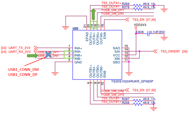
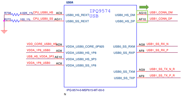
I have an application with TS3DS10224 below.USB2.0 signal from CPU to MUX pin INB+/-, after passing through MUX, connect to the USB port.

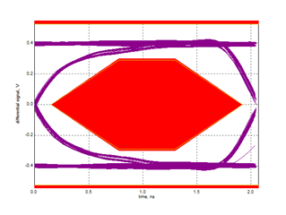
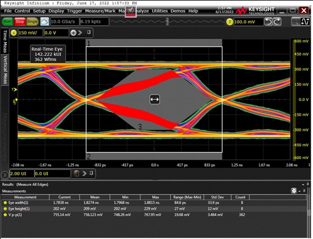
we couldn't pass the eye-diagram test. For tracing the root cause, We probe the INB+/- side and got the distorted eye diagram below.
We tried to remove MUX and short the empty section, then the eye diagram can pass.

So I doubt the MUX is impedance mismatch with my circuit.

Could I know the load Impedance of TS3DS10224?

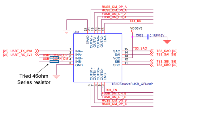
And should I add some resistor for Impedance matching?

(My net impedance is 90ohm Zdiff, trace length from CPU to MUX is 2900 mil)

thanks.


  • Hey WeiChen,

    So the load impedance will be dependent on a few things here. The CON, the RON and the frequency of the signal. The BW of the device is 1.2GHz so it should be able to handle it but you may be seeing losses do to the matching, as you guys are hypothesizing right now. I believe that adding some resistance to match the trace better may help with the eye diagram tests. At higher frequencies the impedance should be closer to the RON. Could you try adding some resistance and seeing if it helps? I would start with something closer to 70-80ohms to try and match the 90ohms Z of the system.

    Let me know how it turns out.

    Thanks,
    Rami

  • Hi Rami:

    Could I check the precise configuration of your suggestion?

    Should we add resistances next to the mux as series resistance, or do we need to terminate resistances to GND?

    Thanks.

  • Hey WeiChen,

    You'd want to put the resistor in series here as you're going from a higher to a lower resistance and are aiming to increase the impedance

    Thanks,
    Rami 

  • Hi Rami

     After adding resistors, our eye-diagram became worse than before, as below

    If we bypass the MUX, our result will be below

    Could you help us check out schematic if there is something can improve?

    And we perform 1:4 on INA & INB both at same time, INA is UART signal, INB is USB2.0 signal.

    Thanks

  • Hey WeiChen,

    I'm noticing now that the eye diagram looks like it has some negative voltage. Can you bias this and run it with strictly positive voltage? The device isn't rated to handle negative voltages. 

    Additionally, what resistance values have you tried? Have you tried tweaking this value and seeing the results?

    My net impedance is 90ohm Zdiff

    Could you clarify this value for me? I may have misinterpreted it. Is this the trace impedance of each INB+ and INB- trace? Or is this the differential trace impedance between INB+ and INB-?

    I believe this value was actually the differential impedance which wouldn't be as straight forward to resolve. You may need to probe the individual traces without the mux to give an idea of what the trace impedances are before. Then we can try and add the appropriate traces to match the impedance.

    Additionally, what is the purpose of the trace with R269 and R278? Are these going to some other device? Right now, it looks as if you're just pulling the output to ground. If this is the purpose, why does the eye-diagram matter here if it isn't a communication pathway?
    Seeing the board layout may be helpful for me to try and identify what is going here as well, if you're comfortable sharing this.

    The rise and fall times impact the eye diagram more than the actual working frequency. The device itself can handle quite a high frequency (500MHz - 1.2GHz depending on the configuration), so I would think that any UART signal (<50MHz) wouldn't be an issue. Are you seeing actual problems with communication in the system?


    Thanks,
    Rami

  • Hi Rami:

    ok, I restate my condition and update the current schematic as below. (R269&R278 were removed and connected to the rear port)

    My application is USB 2.0, INB to OUT A0.A1.B0.B1(FUSB means front port, RUSB is the rear port), impedance is Zdiff=90ohm (for the single end is about 45 ohm)

    INA is for UART and it shares the same OUT channel with USB2.0.

    The eye diagram was measured as the voltage difference between differential pairs, so there was a negative level when positive pin=0 & negative pin=1

    All Ports failed in the eye diagram test and got similar results as below (measured at USB connector)

    We added 46 ohm series resistor for the previous trying to make impedance match but didn't make it better.(measured at USB connector)

    After bypassing the MUX, All ports can pass compliance as below(measured at USB connector)

  • And We used core wire to connect when we bypass the MUX

    I think in this situation, the impedance match should be far away from our expectations.

    So I suppose maybe the impedance match is not the root cause of this issue.

  • WeiChen,

    Have you tried any other values and seeing how it affects the system? Actually measuring the impedance and adjusting as needed per signal path would be recommended here.
    I'm not an expert in transmission line and matching but I do have some knowledge that I can try and help with. I believe maybe there was a misunderstanding on R269&R278. If the objective is to connect these to the rear port, I believe these are termination resistors to match to 50ohms actually. The rear port probably has an impedance of some Mega-ohms, so you'll want that parallel 50ohm termination resistor there to match the load impedance with the 50ohm characteristic impedance. otherwise, the reflection will be significantly worse. Since the device has some resistance, and you're aiming to match that too, the source impedance (those two extra resistors added) may need to be lower.  

    That being said, I'm also a bit skeptical that the impedance mismatch is having such impact. However, the device should be able to handle this frequency. Have you tried testing basic communication through the device to see if the signal is actually being affected? What is the actual operating frequency you're looking to work with?

    Additionally, how wide spread is this issue? Is it just on one device or across many? 

    Another thing that i'm curious about is why the correct eye diagram is run through a different setup than testing the board with mux. It's not a good side by side comparison if you're running the tests differently. Can you provide an eye diagram through the software and same test setup as the mux is going through but bypassing only the mux alone but still going through  the rest of the board?


    I'm noticing that this is the same question as this thread 
    https://e2e.ti.com/support/switches-multiplexers-group/switches-multiplexers---internal/f/switches-multiplexers---internal-forum/1111540/ts3ds10224-u2-uart-switching-with-ts3ds10224

    Was this layout revised since the issue was seen here? Looks like in the differential pairs, the length matching was fixed periodically through the inner trace. This may be affecting your signal as your shifting the noise differently. The length matching should be done at once at the end of the signal.

    Thanks,
    Rami