This thread has been locked.

If you have a related question, please click the "Ask a related question" button in the top right corner. The newly created question will be automatically linked to this question.

SN74LV4051A-Q1: SN74LV4051A-Q1 schematic proper R, Cap value

Part Number: SN74LV4051A-Q1

Hi Experts,

Could you please recommend the proper R, Cap values or additional element for this schematic? (Pull-up R / Decoupling cap, etc) 

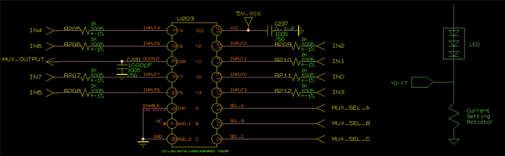
Multiplexer IC SN74LV4051A-Q1

( VCC 5V / Input : LED cathode / Output & Chip Selector : MCU )

Thank you.

  • For the decoupling capacitor, 100 nF is fine.

    The other component's values depend on whatever your unknown application needs; the multiplexer itself does not care.

    The ground pin should not be left open.

  • Hi Dustin,

    0.1uF is the typical recommendation for decoupling capacitors for our devices, so no issue there. In terms of the pullups, there is no dependency from the mux itself on which pullups you need to use, that will be dictated by the application you are using them in.

    Lastly, as Clemens mentioned, you need to make sure to not float the GND pins. All GND pins should be connected to the GND reference on your board.

    Thanks!
    Bryan

  • Thanks for your reply! How about 1000pF? which is on COM line.

  • That is not a decoupling capacitor. It looks as if this is intended to form a low-pass filter together with the resistors. But I do not know what the goal of this LPF is.

  • Hi Dustin,

    Again, this will be determined based on the application on whether you need it there or not. The 1000pF capacitor will act as a low pass filter as Clemens pointed out, but also will impact the switch timing parameters on the channel to be slower as well since the device needs to charge and discharge that capacitor everytime the switch turns on/off.

    Thanks!

    Bryan

  • Hi Bryan,

    Thanks for your reply.

    I think I should consider the current value which can flow into SN74LV4051A-Q1 on Y# line.

    Y0~Y7 get input from cathod of LED.

    So, the current depends on "Current Setting Resistor" and Resistor on Y# line.

    Could you please advise the proper Resistor on Y# line? (R205, R206 ~ R209, R212)

  • The switch itself does not care (as long as you stay inside the 25 mA limit).

    The resistors limit the current, have a voltage drop, and affect the LPF. These are choices that you must make, depending on what the goal of this circuit it.

  • The purpose of Y# is to check the open status of LED line. So, it need to sense 0V (LED open).

    Dose this purpose affect on choosing R205 ~R212 values?

    And I don't understand the LPF you said. 

    Did you mean the LPF which can be made with parastic cap & R205?

    Or Dose this device has LPF internally?

  • How do you sense this, with an ADC or a comparator? What is limit of the impedance of the ADC's input signal?

    The resistor and capacitor form a low-pass filter. Why is there the capacitor? Is it recommended for the ADC input?

    At what frequency are you sampling the ADC?

  • Dustin,

    The value of the R205-R212 values will be calculated based on the maximum current you expect to see through the multiplexer channels. You need to keep the current through each channel of the mux to be less than 25mA. This will be determined by the load on the mux output. If the mux output is feeding to a high impedance input, then you will not need any resistors on the inputs as there will be minimal current flow into the mux channels. If it is not a high impedance input and the current that would flow through the mux would be greater than 25mA, then you need to size your resistors accordingly to limit this current.

    The low pass filter is constructed by the the parasitic capacitance of the mux and the rated resistance of the mux as well. This forms an RC filter (low pass) that will determine how fast of a signal can propagate through the mux without being attenuated (we specify this on our parts as "bandwidth" which for this device would be 35MHz).

    Thanks!

    Bryan

  • Thank you Clemens!
    I fully understand the point from your questions.
    The C220 and R205~R212 form a LPF, so we should consider the sampling frequency.