The TI E2E™ design support forums will undergo maintenance from July 11 to July 13. If you need design support during this time, open a new support request with our customer support center.

This thread has been locked.

If you have a related question, please click the "Ask a related question" button in the top right corner. The newly created question will be automatically linked to this question.

TS3A5018: SPI clk has non-monotonic in 2 MUX cascaded

Part Number: TS3A5018
Other Parts Discussed in Thread: TMUX1574

Hi TI teams,

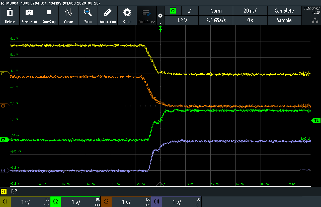
We found that TS3A5018 has non-monotonic in our clock signal as below figure.

We've checked the layout equal length. 

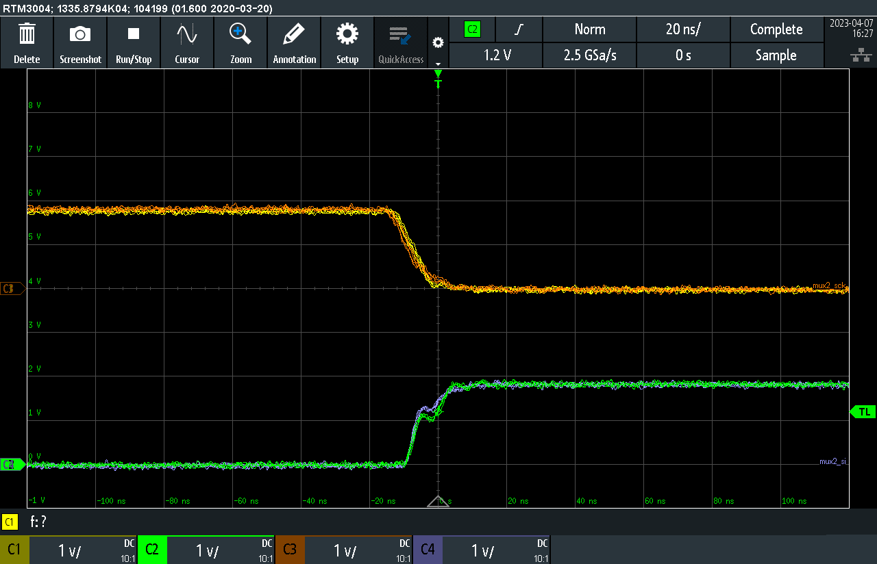
However, we found that using TMUX1574 without non-monotonic.

The same hardware and firmware. May I know what is going on.... thanks.

BR

Helen

  • Hi Helen,

    At first glance this looks to be a difference of bandwidth. The TS3A5018 only has a 300MHz bandwidth while the TMUX1574 has 2,000 MHz. Would it be possible to provide a scope shot of the TS3A5018 from the same source as the TMUX1574?

    Thanks!

    Alex

  • Hi Alex,

    2 diagrams as above are the same hardware topology but different part number.

    BR

    Helen

  • Hi Helen,

    It looks like the frequency being used for TS3A5018 is 373.1MHz, is this correct? If so, this is beyond what the device is rated for. 


    Thanks!

    Alex

  • Hi Alex,

    It's cursor. I'm sorry about let you confuse.

    BR

    Helen

  • Thanks Helen. Since our switches are just a passive devices this is a strange behavior so I will need some more information. Can you provide screenshots of the control pins and input/output pins as well? I want to see the behavior on basically all pins being used on our switch here. 

    Also is this clock signal shown occurring during actual signal switching or just during a square wave input? If the non monotonic clock signal is happening during signal switching then there's room to explore this issue, but if it's during a regular square wave input then the issue is likely not related to the switch here. 

    Lastly, is there a reason you are wanting to keep using the TS3A5018 over the new and improved TMUX1574?

    Thanks!

    Alex

  • Hi Alex,

    Occurring during the clk signal input. I'm very confused about why passive device is so different in these part number.

    The first time we found that using TS3A5018 in our application for SPI signal debug switching. However, it will fail to decect the slave fail sometimes. Refer the datasheet it could support SPI application. However, we could succees to use when the component change to TMUX1574.

    Our customer side wants to know what is going on for this. Now I found the non-monotonic in clk signal. It would effect the setup time and hold time.

    When using TS3A5018, I rework and jump wire to master only clk, it could success to detect.

    I'm still finding the root cause for our end customer.

    Thanks.

    Helen

  • Hey Helen,

    It's current a US holiday but Alex will follow up on this when we get back tomorrow.

    I do see though that some screenshots were asked for to help our debugging process. Are we able to get any of the ones Alex asked for?
    I agree that this behavior isn't expected so being able to see what the other pins look like will help.
    A believe a schematic will be useful as well.

    Thanks,
    Rami

  • Hi Helen,

    Just following up that we need some more screenshots here to help with debugging the non monotonic clock issue here. If you can provide these along with a schematic, then my team can help look into this as I'll be out of office the rest of the week. 

    Thanks!

    Alex

  • Hi Alex,

    please refer the attached. Some GPIO netname I need to remove, I'm sorry for that.

    Thanks.

    design4.pdf

  • Hi Helen,

    Do you have any screenshots of the layout as well? For signals at this speed (MHz range) sometimes the layout can cause reflections that will appear as non-monotonic, depending on the resistance and capacitance of the system.

    Thanks,
    Stephen 

  • Hi Stepehn,

    Could you share the link or email with us? We could provide this portion board file for your reference. thanks.

    BR

    Helen

  • Hi Alex,

    Could TI teams share IBIS model in 1.8V UQFN case?

    In the website, the file is only in 3.3V case.

    Thanks.

    Helen

  • Hi Helen,

    The TS3A5018 does not have a 1.8V IBIS model unfortunately. The model does have a 2.5V case so you can use that as a means of having a model closer to 1.8V vs 3.3V. 

    Thanks!

    Alex

  • Hi Helen,

    You can reach out to a-vish@ti.com regarding this one!

    Thanks!

    Alex 

  • Hi Alex,

    That’s too bad! I would try it in 2.5V case. Thanks.

    Helen

  • Hi Alex,

    I've sent the email to this address. Thanks for your great help.

    Hope we could find the root cause.

    Thanks.

    Helen

  • Thanks Helen. I will close the thread on this end for now. 

  • Hi Alex,

    Because our setup/hold time of SPI signal is followed the datasheet, and we found the something wrong in clk. As above I describe, we are very confused about that the same hardware but different part number, and the waveforms are better and worse.

    I know TI team would feedback non-monotonic related our layout trace. But the main question is why the same hardware but different part number, and the waveforms are better and worse SPI singal? Please help us to check it. Thanks.

  • Hi Helen,

    After looking at the datasheets again I’m seeing that the TS3A5018 only has 300MHz bandwidth while the TMUX1574 has 2GHz. Since you have a cascading mux application then you are effectively reducing the bandwidth by at least half and taking on 2x the insertion loss. This is likely the cause of your non monotonic clock issue as nothing else stands out that could be causing the issue. So, for cascading TS3A5018 you’re cutting the effective frequency to at least 150MHz and for TMUX1574 you’re cutting it down to 1GHz. A good rule of thumb is that bandwidth should be at least 1.5-2x the Nyquist frequency.

    If you’re able to utilize the TMUX1574 then I recommend using this device over the TS3A5018.

    Thanks!

    Alex

  • Hi Alex,

    Actually, the frequency in our application operate in 1M Hz. It seems that it it could meet the spec 300MHz, even it become 150MHz in in 2 MUX cascaded. Besides, the insertion loss in 1MHz is almost small value.

    We're still wonder why bandwidth will cut half when cascade. I've tried TMUX1574 as above, and we know it could work. However, as reference article mention TSA5018 could support SPI design. 

    However, we still need the root cause and analysis report for our end costomer.

    Please kindly to help us. Thanks.

    Referece:

    https://e2e.ti.com/support/switches-multiplexers-group/switches-multiplexers/f/switches-multiplexers-forum/937905/ts3a5018-is-it-ok-for-spi-application?tisearch=e2e-sitesearch&keymatch=TS3A5018#

    BR,

    Helen

  • Hi Helen,

    Thanks for this information. In this case, I'm interested in the edge frequency as opposed to the clock frequency. Edge frequency is much faster. Can you provide this? Are you or the customer able to slow down the edge and capture what it looks like? If we are looking at a bandwidth issue (which is still not ruled out) then we should be able to slow it down enough to get a clear signal. 

    Thanks!

    Alex

  • Hi Alex,

    Thank you for your understanding. What is the edge frequency define? Could you help us to share it? I'm afraid that I misunderstanding this.

    We're still confuse why bandwidth will cut half when cascade.

    Thanks.

    Helen

  • Hi Helen,

    Sure thing! Edge frequency is basically seeing what the bandwidth of a given signal is using rise time as shown below. 

    Our team is currently working on content around cascading multiplexers which will release later this year, but essentially because you're feeding a signal through multiple devices, you can expect a degradation of bandwidth due to parasitics. This test report shows how noise is introduced when cascading multiplexers using S parameter models. Test Report for Cascade Analog Multiplexers

    Lastly, can you confirm if the customer is able to drop in the TMUX1574 in the case that TS3A5018 is not feasible in this application? We haven't heard of a non-monotonic clock issue with this part in the past so I am still confident this will come down to an issue of bandwidth.

    Thanks!

    Alex 

  • Hi Alex,

    Our rising time is 7.44ns. It seems that we still have enough bandwith for this.

    We got the Test Report for Cascade Analog Multiplexers.

    The part number in reference article is different with TS3A5018.

    In our case, we operate in 1MHz.It seems the IL not impact too much.

    We are very confused this.... why it is still fail when setup/hold time is enough and meet the SPI spec.

    TS3A5018 and TMUX1574 are different with Ron. I try to think about it, how could we provide some waveform for TI team if it is the the debug cause.

    Thanks.

    Helen

  • Hi Helen,

    Thanks for all the information. Yes, any additional waveforms that could be provided would be of much help to help diagnose this unique issue. Please provide those at the earliest convenience.

    Thanks!

    Alex

  • Hi Alex,

    Please refer the attachment.

    We've checked the SPI singal, and compare with only one MUX application.

    It seems that we have enough edge frequency and enough setup/hold time.

    When the clk bypass through 2 MUX cascaded, it could work.

    Please kindly help us. Thanks.

    SPI_0327.pdf

    BR

    Helen

  • Hi Helen,

    In slide #10, with the block diagram of the application - is Master B and C running while A is running? Basically, is a signal going through B and C here? 

    Would you be interested in a device other than the TS3A5018? We are likely looking at some sort of layout issue with the device and will ultimately have to settle on a different part here. 

    Thanks!

    Alex 

  • Hi Alex,

    In slide#10 

    Is Master B and C running while A is running? ==>  No, only master A running.

    We would try to use TMUX1574 in our application. However, we still want to know why cause it...

    What's the next debug step we could try, any suggestion? 

    Thanks.

    Helen

  • Hi Helen,

    We ran a cascading mux experiment in the lab with the TS3A5018 and we do not see the non-monotonic clock signal. Have you tried to swap with another TS3A5018 part in case the current one is damaged? 

    Thanks!

    Alex 

  • Hi Alex,

    I will try to rework new sample but I apply some sample from our sourcer.

    I'm sorry for it when I get the sample, it would approach our national holiday.

    I need to try it after 4/6 in Taiwan's time.

    As waveform, does it seem that we have part compatibility issues or Impedance matching issue?

    Thanks

    Helen

  • Hi Helen,

    Based on what we have seen it appears to be related to a part compatibility issue more than an impedance matching issue. Please let me know the results of the sample swap so we can arrive at a solution for you!

    Thanks!

    Alex 

  • Hi Alex,

    I've tried the new TS3A5018 to rework in 2 TS3A5018 cascaded. The non-monotonic still exist it.

    It seems that not the TS3A5018 damaged issue. As through TS3A5018, SPI signal (1MHz applciation) is attenuated and has non-monotonic.

    When through 2 MUX cascaded, the position of non-monotonic would impact our data.

    We still need your help to analysis. Thanks.

    ▼ Figure1. SPI topology

    ▼Figure 2. Measure front TS3A5018 input/out of SI/SCK.

    CH1: HDR_SCK

    CH2: HDR_SI

    CH3: MUX2_SCK

    CH3: MUX2_SI

    ▼Figure 3. Measure front TS3A5018 input/out of SI/SCK.

    CH1: HDR_SCK

    CH2: HDR_SI

    CH3: MUX2_SCK

    CH3: MUX2_SI

    ▼Figure 4. Measure back TS3A5018 input/out of SI/SCK.

    CH1: LEO2_SCK

    CH2: LEO2_SI

    CH3: MUX2_SCK

    CH3: MUX2_SI

    ▼Figure 5. Measure back TS3A5018 input/out of SI/SCK.

    CH1: LEO2_SCK

    CH2: LEO2_SI

    CH3: MUX2_SCK

    CH3: MUX2_SI

  • Hi Alex,

    Is there any possibility about metastability phenomenon? Thanks.

    Helen

  • Hey Heen,


    We're on holiday today in Dallas for Easter. Alex will get back to you with a response on Monday 4/10

    Thanks!
    Rami

  • Helen,

    I'm not familiar with metastability, so I can't comment on this. Most likely reflections are causing the non monotonic clock signals. TMUX1574 as discussed has higher bandwidth, but also has much better Off Isolation, which would reduce potential reflections in the switch.

    If we go back to the rise time of 7.44 ns that you indicated, this translates to ~130 MHz. For sensitive signal chains, we recommend ~3x bandwidth as highlighted in our FAQ, so even without the cascading effects, we would recommend a part that can handle at least 390 MHz. It appears the TS3A5018 will not work in this target application and TMUX1574 will be the ideal working replacement. 

    Thanks!

    Alex 

  • Hi Alex,

    1. Why need to extra 3x bandwidth when the cascaded?
      As the mention about rise time of 7.44 ns, this translates to BW~=47 MHz. 3x bandwidth =141 MHz.
      I'm not sure why need to extra 3x bandwidth ~=423 MHz when we cascaded the MUX TS3A5018.
      It seems that point to point circuit.
    2. They are different ON-State Resistance. Is it cause the reflections?
      After checking, TMUX1574 and TS3A5018. The former one is 2 ohm and the other is 10 Ohm.
      It seems that point to point circuit, Is it related to impedance miss matching?

    I still have some concern about this. Please help us to check it.

    Many thanks.

    Helen

  • Hi Helen,

    As mentioned in the FAQ, "frequency composition of a square wave has a fundamental frequency and many harmonics while a sine wave frequency composition is a single fundamental frequency. To account for this, it is good practice to select a device with the listed bandwidth as 1.5 times the square bandwidth calculated above. For highly sensitive signal chains, it is best practice to select a device with 3 times the bandwidth."

    For this reason, we want to select 3x bandwidth as a best practice for sensitive signal chains. For a rise time of 7.44ns, if we translate this to frequency (f=1/T), then we get 134MHz. So 3x is ~400MHz. 

    On resistance can also have an effect as you mentioned, so the ideal part would have high bandwidth and low Ron, such as the TMUX1574.

    Thanks!
    Alex