This thread has been locked.
If you have a related question, please click the "Ask a related question" button in the top right corner. The newly created question will be automatically linked to this question.
Dear TI,
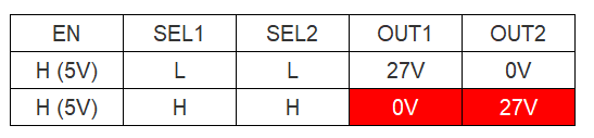
I would like to configure the circuit with the following configuration.
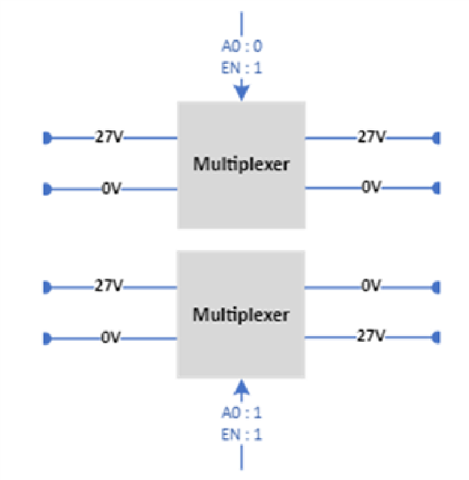
That is, I want to implement a way to cross input and output.
Such a crossing can be implemented with SPDT switches like the TMUX6236. Connect one input to S1A and S2B, and the other input to S1B and S2A.
Hi Bub,
The methodology Clemens laid out will work for crossing your inputs and outputs. Connecting one input to S1A and S1B and the other to S1B and S2A (or vice versa) will work since the device is bidirectional.
Let me know if you need anything else here!
Thanks!
Alex
Hi Clemens and Alex,
Thank you for your attention and support.
VSS is the negative supply and must be connected to GND.
VDD is the possitive supply and must be connected.
Dear Clemens,
Thank you for checking for errors.
Even if you proceed with the test by changing as follows, only one direction is still possible.
OUT1 | OUT2 | Test result |
27V | 0V | Ok |
0V | 27V | No |
Hi Bub,
To be completely sure, you are toggling SEL pins high when enabling the S1A/S2A to D1/D2 path?
Regards,
Alex
Hi, Clemens and Alex,
Thank you for your support.
The signal level is applied with DC power. (5V)
EN | SEL1 | SEL2 | OUT1 | OUT2 |
H (5V) | L | L | 27V | 0V |
H (5V) | H | H | 0V | 27V |
And what happens instead? What do you measure? What is the voltage at the SEL pins?
Hi Clemens,
Sorry for the late reply.
The output to each pin is output as 0V.
When the SEL 1and 2 pin is in a high(5V) state, the output does not cross and is measured as 0.
This should not happen. Can you measure the resistance between the S and D pins?
If you applied the wrong VSS/VDD voltages to this chip, it might have gotten damaged. In this case, replace it.
Hi Clemens,
Thank you for your support.
We plan to purchase additional parts and test them as follows.
Do you have any further guidance on this?
Also, can you test it with an actual circuit configuration and share it?
Hi Bub,
It's unlikely Clemens would do the testing as he is a magical Guru that pops in to help out with various E2E's, but is not a TI employee. I urge you or the customer to perform the testing and let us know the results. Please follow up with the results as soon as you have them so the team can help out as needed.
Thanks!
Alex
Hi Alex and Clemens,
I understand what you mean.
Testing will begin again when the board and new ICs arrive.
The test conditions are as follows.
- Single input : DC 27V
- EN, SELx Pin Input : DC 5V
- SxA and SxB Input : DC 27V and GND
If you have any problems with the above conditions, please comment.
Thank you.
Hi Bub,
Sorry for the delay here! The setup looks good so please let us know the results of the testing.
Thanks!
Alex
Hi Alex and Clemens,
Thank you for your support.
This issue has been resolved.
It was a ground problem with the logic power supply and the main power line.
Hi Bub,
That is great to hear!! Thank you for posting to our E2E forum so we could help bring you to a solution.
Thanks!
Alex
Hi Alex,
Once again I ran into a problem.
I want to control SELx with PWM.
What is the maximum controllable frequency range?
As a result of the current test, control is impossible from 1Khz. SELx recognizes all of them as H status.
Is there any other product that can control more than 10kHz?
The turn-on and turn-off times are specified as much less than 1 µs. This should work.
Please show an oscilloscope trace of the SEL input and the I/Os.
Hi Clemens,
Thank you for your support.
-> Positive Pulse : 9.9uS / Negative Pulse : 10us
Hi Clemens,
The above waveform is applied from the MCU port to the SEL pin.
The problem is that even when a waveform is applied, the output does not cross, and it recognizes only high and outputs 0V and 27V.
In all the circuits shown above, the SEL pins must have the same value.
Did you change the circuit?
Hi Clemens,
Sorry for the delay.
No part of the circuit has changed.
In the past, the test was conducted by giving a signal of 5V or 0V to the SEL Pin.
-> For the test signal, On/Off was manually controlled with a DC Power Supply.
Currently, it is combined with an MCU and receives signals using the I/O Port.
-> Is there a problem with the signal currently set up?
-> If you control it manually, which is the old way again, it works.
The output terminal is checking the voltage change with a digital multimeter.
The waveforms show two different SEL signals. But you should have a single signal for both SEL pins.
Hi Clemens,
Thank you for your support.
Does this happen if the ground levels are different?
When testing with the power supply, the ground level was the same.
I think it's a problem because it's currently in the board(TMUX6236)-to-board(MCU) test.
Hey Bub,
This could happen if the grounds are different potentials but I don't think this would be the cause. A quick test here would be to simply tie your grounds together. Just get some wire and touch both your MCU board and your TMUX6236 board grounds together.
It is interesting that the PWM isn't working but manually toggling is. Your transition times are in the 100ns range while you're toggling at 10us so I don't think the limiting factor here is the timing.
Try doing this one SELx at a time. Just make sure you can toggle a single channel first with a PWM. Nothing you've shown indicates that it shouldn't be working.
Another note to simply the circuit for you, are the GL and GH in your scope shots coming from two different sources and going to SEL1 and SEL2? You can really just use one source and connect it to both the SEL1 and the SEL2 pins for your final design.
Thanks,
Rami
Hi Rami,
Thanks for the advice.
GL and GH signals are PWM signals generated from GPIO of MCU, and these signals are used as input signals for SEL1 and SEL2 respectively.
A test was conducted to control SELx with one signal, but it is recognized only as High status as before.
Thanks,
BJ Han
Hey Bub,
Thanks for checking. Have you tied the grounds together and tries the test?
The only other thing I can think of currently would be to replace the device and try a new it on a new device. There could be some damage (perhaps ESD) to this specific device you are using.
Hi Rami,
Thanks for the advice.
After replacing it with a new one, the test showed that there was a problem with GND and signal processing.
As a result of unifying the GND settings of the 3-Board and controlling the SELx pin with one signal line as shown below,
normal operation was confirmed as in theory.
Thank you for your support.