This thread has been locked.

If you have a related question, please click the "Ask a related question" button in the top right corner. The newly created question will be automatically linked to this question.

TMUX2889: Output attenuation problem, when input is a PWM signal(600KHz)

Other Parts Discussed in Thread: TMUX2889, TS5A23160, TMUX1072, DRV2605, TS5A26542, TMUX6234

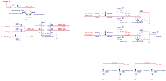
part number: TMUX2889

Hi TI,

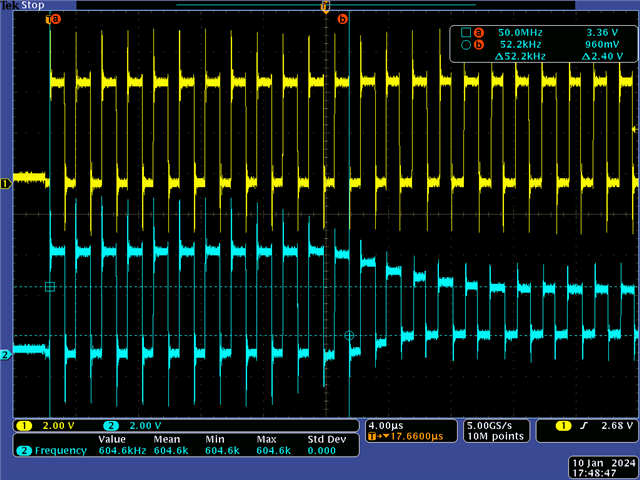
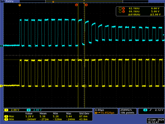
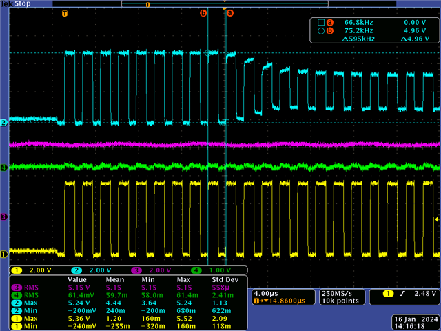
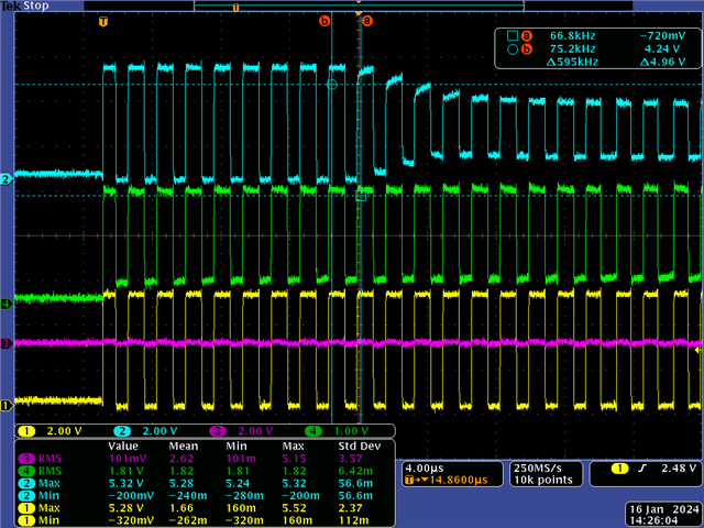
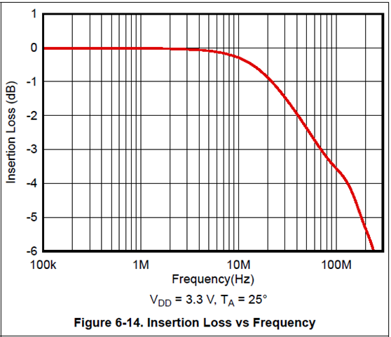
In the TMUX2889 datasheet page. 10 - Figure 6-14. Insertion loss versus frequency,

We can see there is no insertion loss at <1MHz.

But we send the 600Khz/5V PWM signal to the D1/D2 pin as input.

After 10 cycles we see voltage decay.

CH1 => TMUX2889 D1 pin, CH2 => TMUX2889 S1A pin.

Why?

  • As shown by the over/undershoots, there is no bandwidth problem.

    What is the supply voltage? What is the load on S1A? Please show a schematic.

  • Hi Clemens,

    But, I saw another person asking a similar question in the forum. => TMUX2889YBHEVM: PWM signal pass though issue - Switches & multiplexers forum - Switches & multiplexers - TI E2E support forums.

    Schematics as below.

    Load for S1A and S2A , it is a LRA.

  • Hi Clemens,

    I add series resistors on D1/D2 input to reduce over/undershoots,

    But I still see voltage decay, FYR.

  • Hey Delo,

    It's currently a US holiday so expect a more thorough response tomorrow but from a quick inspection of this, it is interesting that it happens after 10 cycles. Is there anything else happening at this moment? Could you check the power supply and control pins as this event occurs?
    I'd also like to see the other unselected channel S1B to see if there is maybe some shorting happing on the S1B and S1A paths that is creating a divider. Let's first try and see where the voltage is being split. It will help determine what is happening. 

    Thanks,
    Rami

  • Hi Rami,

    CH1 - D1 pin, CH2 - S1A, CH3 - power VDD pin, CH4 - control SEL pin

    no SEL change, no power drop.

    About S1B, we can measure a similar waveform, but the SEL pin is low at this moment.

    I used power meter to check it, but there is no shorting between S1A and S1B, it should not see this PWM waveform on S1B, FYR. 

    CH1 - D1 pin, CH2 - S1A, CH3 - control SEL pin, CH4 - S1B pin

  • Hey Delo,

    I looked into this further and it looks like the issue comes with the larger swings. The device is typically meant for audio applications; so smaller voltage swings and lower (<20kHz) frequencies. 5V @ 10MHz is considered a large swing for the frequency for this device so the gate has a little trouble keeping up.
    That being said, it does look like you're using a single sided supply and passing a strictly positive signal through the switch (0 to 5V). Is there a reason you selected this device? 
    Could something like the TS5A2654 work here? Still a 2ch 2:1 with low RON and can support up to 5V. It's a different architecture than the TMUX2889 so the swing shouldn't be an issue. 
    If you need powered-off protection (Switch isolated when VCC = 0V) the TS5A23160 could also work.
    If you need powered-off protection AND a dedicated enable pin to turn both channels off, the TMUX1072 would be the best low RON, 5V option.

    Let me know if any of these works for you or if you have any other questions.
    Thanks!
    Rami

  • Hi Rami,

    We would like to use a 1:2 MUX for PWM signal (likes DRV2605 output).

    If the max. swing is 10V @600KHz in LRA calibration mode.

    Do you have the suggested component?   

  • Hey Delo,

    I'm a little confused on the criteria here. The waveforms you sent are 10MHz and a 5V swing and a 5V supply but your ask is a 10V swing and 600KHz.
    So I can help find a suitable part could you please be more specific on the supply, frequency and actual I/O voltage (swing) that you'll be needing?

    Thanks,
    Rami
     

  • Hi Rami,

    Our waveform should be 5V@600Khz PWM signal, why do you mean 10MHz 5V swing?

    the normal working mode is 0~5V swing PWM signal, but Haptics driver will use a Max. 10V swing PWM signal in LRA calibration mode. 

    That's why I asked about the max. 10V@600Khz. if 10V input is not a common component, we can keep to use 5V 600Khz for MUX input requirement.

    We can fix our PWM output to keep MAX. 5V output.

    VDD = we can provide 3.3V or 5V power supply, IO input = 0~5V @ 600KHz (10V is better), LRA Max. current requirement = 130mArms, Control SEL pin = 1.8V GPIO output. 

    Thanks~

  • Hey Delo,

    I think I had a typo earlier in the conversation of 10MHz instead of 1MHz and confused myself of the frequency. Sorry about that. Thanks for clarifying your needs 

    So unfortunately I don't think we have a perfect fit for all the system needs but the closest fit I could find are the following: 

    TS5A26542 is a 2 ch 2:1 like the TMUX2889, can support up to 5V and 600KHz and peak switch current up to 700mA so your 130mArms will be fine. The only issue is the VIH/VIL levels aren't 1.8V logic compatible. You could add a translator on the control inputs to make them compatible though. 


    TMUX6234 will be another option if the current can be restricted at all. The 6234 will be able to support a 5V supply and the 5V I/O requirements (not the 10V unfortunately, unless you added a 10V rail). But at 5V supply it won't be able to support your 130mArms (~380mA peak) current.
    It will be 1.8V logic compatible. 100MHz bandwidth should support the 600KHz signal pretty easily.


    Thanks,
    Rami

  • Hi Rami,

    Could you help to apply TS5A26542 EVM for me?

    I would like to verify it on our board, first.

    thanks~

  • Hey Delo,

    Unfortunately, I did a thorough search and I couldn't find any boards through TI that we have that are currently compatible with this footprint.

    Thanks,
    Rami

  • Hi Rami,

    Thanks, I will find local FAE to find the EVM or other support.