This thread has been locked.

If you have a related question, please click the "Ask a related question" button in the top right corner. The newly created question will be automatically linked to this question.

TS5A22362 Switching Error

Other Parts Discussed in Thread: TS5A22362

Hello,


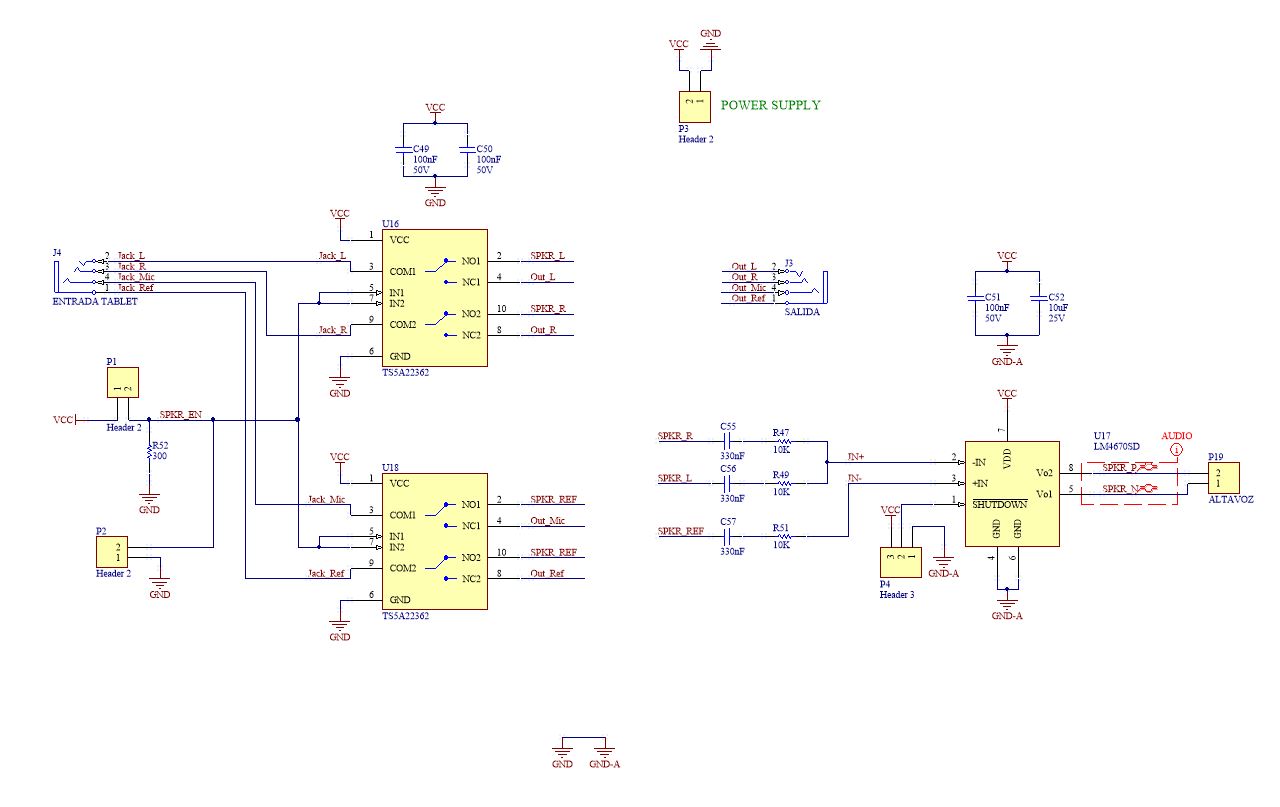
I am using the TS5A22362 for switching audio audio from a Tablet to an Audio Amplifier or to a 3.5mm Plug.

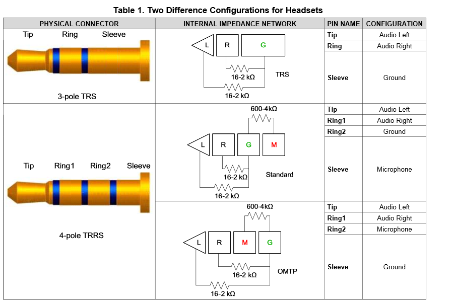
Since the 3.5mm plug has 4 signals, I'm using two TSA22362 for switching the four signals.

The 3.5mm Plug signals are connected to the NO pins. and the Audio Amplifier is connected to the NC pins

The problem is, when I toggle the IN control signal from the NO to the NC pins, because it makes the change, but when playing music from the Tablet (COM), I can still hear the sound on the NO (that is not longer connected), it hears lower, but I can hear it.

Can you help me, please?

  • Adair,

    Do you have a schematic showing your connections of the system you describe? This can help us work through the remote debug seeing how you are connecting the two TS5A22362 switches and routing to the tablet, 3.5mm plug, and audio amp.

    How are you hearing the unwanted sound? Through headphones connected to the 3.5mm jack?

    Thank you,
    Adam
  • Hello Adam,

    The unwanted sound is some king of noise, and the music with lower volume

    Attached is the schematic. This eschamatic w made for a prototype so i could test the circuits and them, once it would be tested and working, put it on the final schematics

  • Adiar,

    The unwanted sound is some king of noise, and the music with lower volume are you hearing through the tablet or headphones or a speaker? Are you hearing the correct sounds out of the selected path in addition to the unwanted sounds on the unselected path?


    The schematic did not attach can you please send it again.

    Thank you,
    Adam
  • Hello,

    Let's say , I connect a tablet to the J4 connector (COM1 and COM2 of U16 and U18). And normally, I am switching the sound from the Tablet to the J3 connector ( NC1 and NC2 of U16 and U18). ... But when I switch to NO of pin of both switches. the sound should stop be heared in J3, and only be heard on the audio amplifier, right?


    And the sound is being hear on the audio amplifier, but it is also heard on the J3 connector (with lower volume)

  • Adair,

    What you describe above is a correct use case for the TS5A22362.  


    What do you have plugged into J3 that you can hear the audio?  Does it have a lot of gain?

    Do you have a layout of your board?  There maybe be signals coupling causing your cross talk issue


    Do you have any scope shots of the signal going into COM and the outputs of NO and NC in both logic positions?  The TS5A22362 is not a perfect switch as there will be some leakage through the unselected signal path.  We would like to verfify that this leakage is within the specified values. 

    What is the amplifier you are using in the schematic?

    What type of male 3.5mm connector are you using to plug the tablet into your system and connecting to J3?  Is it a 3-pole or 4-pole connector?  You can tell by counting the rings on the connector. 

    Thank you,

    Adam

  • Hello,

    The input is not J3, the input is J4, and on it, I attached an Android Tablet, for the Audio Signal, so is the normal gain acceptable for Headphones

    On J3, which is the output, I will attach a headphone or free-hands.

    The amplifier I am using is one of yours, the LM4670SD with 200K resistors. This board was made just for testing the ICs, and for this, I used a 3-pole connector, so, the Pins 4  of the plug connector are not used. But on the final design, I will use a 4-pole conector, and for selecting between the two different GND and MIC connections, I will use a header.

    But, this header will only be usefull for the Audio Amplifier.... But the output on J3, the signals are been connected "directly", i mean, pin1 to pi1, pin2 to pin2, pin3 to pin3 and pin4 to pin4.... For avoinding the two different connections on the 4-pole versions.


    Here is the layout of the Prototype

    I'll wait for your comments

    THANK YOU

  • Adair,

    I have reviewed the information you have provided and I feel like I am missing something as to why you are getting a signal on the off path. I will forward this to our systems engineer to see if he can notice something we are missing.

    Could you provide a scope shot to showing the logic signal, the desired input, the desired output, and the undesired output?

    Thank you,
    Adam