This thread has been locked.

If you have a related question, please click the "Ask a related question" button in the top right corner. The newly created question will be automatically linked to this question.

TS12A44514 as Resistor Switch

Other Parts Discussed in Thread: TS12A44514, TS5A22362, TS12A4516

Hello,

I'm using the TS12A44514 as a resistor switch as a part of PGA, using the following schematics:

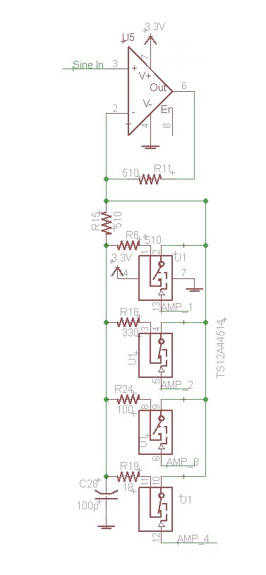
R11 is the RF, set to 510 ohm, and RG = R15 || R switch.

It is a non-inverting topology so the Gain = RF/RG +1;

I place C28 in order not to have DC gain but only AC.

The problem is that the switches AMP2 and AMP3 will not be closed from some reason. There is a chance that switches AMP4 and AMP1 is working by luck.

I'm not sure what am I missing.. Do I affect somehow the Vgs to be less the Vth from some reason ?...

Please Advise.

Thank You.

Eran.

  • Eran,

    I see that you are wanting to pass an AC signal through the TS12A44159 device that does not have a DC bias.  The TS12A44159 devices cannot pass a signal <0 V as seen in the recommended operating table below.


    You either need to apply a common mode voltage to raise your signal swing from going below 0V or use a device that is capable of handling a negative signal like the TS12A4516 or TS5A22362 type of device.

    Additional information:  These types of switches are solid state switches and unfortunately are not a 0 ohm wire.  There are parasitic series resistances on the signal path which you can see in the Ron parameters in the datasheet. 

    Thank you,

    Adam

  • Thank You Adam.
    The AC is around Vdd/2 due to the fact of the connection to IN- of the Amp.
    At any case I found out that the chip I used (and another one) was somehow damaged.
    Now it is all working well!
    Thanks.
    Eran.