This thread has been locked.

If you have a related question, please click the "Ask a related question" button in the top right corner. The newly created question will be automatically linked to this question.

TS12A12511: Offsetting power supply voltages

Part Number: TS12A12511
Other Parts Discussed in Thread: ADS131E04

Hello:

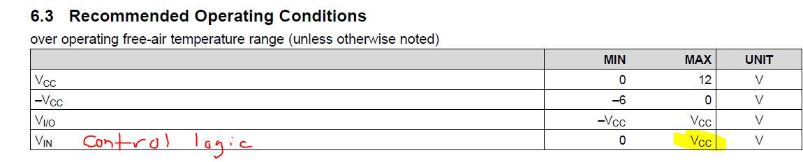
I assume the control voltage of the part must not exceed the positive supply, though that is not crystal clear in the data sheet. In fact, the data sheet implies that is not necessary on the first page when it claims "3.3V and 5V compatible digital control inputs".  I also note the minimum split supply called out as +/-2.7V.

The system I need to design this part into uses +/-2.5V for the TI ADS131E04 ADC, and also has available 3.3V for control signals. 

It would seem I have two options here:

1.  Run this analog switch at +/-2.5V, which is a little out of spec, and divide down the 3.3V logic to be 0 to 2.5V for control purposes (If that front page data sheet claim is misleading).  Would the part be expected to reliably function as a switch under these slightly reduced voltage conditions? It is a low impedance switch, and if its typical 5 Ohms is moderately higher impedance under these +/-2.5V conditions that would be fine. 

2.  Run the part with unbalanced supplies, specifically +3.3V and -2.5V.  This avoids any level translation on voltage control, and maintains higher total voltage on the part than the apparently desired minimum of 5.4V.  I see nothing in the data sheet that would suggest this would not work, other than that the negative supply is not <-2.7V.  Would there be any problem with this?

Thanks,

Farron Dacus

  • Farron,

    The recommended operating conditions sate that the control logic pin is referenced to Vcc so you will need to have Vcc = 3.3 V if you wanted to support 3.3 V on the control logic pin without level shifting.

    You are correct, I don't see an indication in the datasheet that you cannot run the device with unbalanced supply voltages.

    It looks like option number 2 will be your best bet to not have a level shift on your control logic pin.

    Thank you,

    Adam


  • Hi Adam:

    Thanks for the prompt reply.  I do have one other question I would appreciate your taking on.

    The part can operate single sided or split supply.  When split, the minimum supplies are listed as +/-2.7V.  When single sided, the minimum supply is listed as +2.7V, not 5.4V.   

    Do you think it is really true that the negative supply should be -2.7V or more negative?  Based on the minimum positive supply, it would seem more logical that the minimum split supply should be +/-1.35V.  The part does have internal level translation or creation for the negative control voltage, so it seems with +/-1.35V the minimum 2.7V control voltage range would be created. 

    Thanks,

    Farron

  • Farron,

    The recommended operating conditions doesn't really list a minimum potential difference between Vcc and -Vcc.  The device will likely work with slightly smaller potential difference but the performance will be worse as the Ron will increase as the potential difference between Vcc and -Vcc decreases. 

    Thank you,

    Adam

  • Hi Adam:

    Sorry to be difficult, but the problem I'm having is that the recommended operating conditions are creating a conflict of understanding.  With only a positive supply, the minimum voltage from Vcc to Vee is 2.7V, and this creates a certain switch impedance that should be matched with split supplies of +/-1.35V.  But, with split supplies the minimum voltage from Vcc to Vee is called out as 5.4V.  So, CAN the part be operated at +/-1.35V, or is there some control voltage problem that occurs in getting the 2.7V available on the gate to source voltages of the switches? Is it possible to ask the designers of the part about this?

    Thanks,

    Farron

  • Farron,

    With single supply operation the minimum voltage on Vcc should be kept at 2.7V. 

    With dual supply operation you need to make sure that +Vcc is also > 2.7 V because the control logic is based off the potential difference between +Vcc and ground pin.

    You are correct supplying the device with smaller potential difference between the V+ and V- will increase the on-state resistance.  You are also correct that the Vih level will shift based off of the voltage supplied to the V+ and GND pins.

    Thank you,

    Adam

  • Adam:

    Sorry for the stubbornness here, but you are not actually answering the question I am asking. 

    That question is: When a negative supply is used with a positive supply of at least 2.7V, can the negative voltage be between 0 and -2.7V?

    Thanks,

    Farron

  • Farron,

    Yes, the power supplies do not need to be symmetrical.

    Thank you,

    Adam

  • Adam:

    Thanks for the prompt reply.  I apologize for being so nit picky about this, but I am somewhat being forced forced to by the data sheet on the front page saying that the allowed supplies are either a single supply of +2.7V to 12V, or a split supply of +/-2.7V to +/-6V.  Those would appear to be examples of usable voltages, but not actually the required voltages.  It would thus appear that the data sheet is in error, and it should read that:

    1.  The positive supply must be 2.7V or greater. 

    2.  The negative supply can be any voltage so long at the difference between the positive and negative supplies does not exceed 12V.  

    Is that the fully correct and complete way of stating the requirements and abilities of the part with respect to its power supply voltage?

    Thanks,

    Farron

  • Farron,

    The front pages of datasheets are summaries of the device and not detailed specifications.  The detailed specifications can be seen in the table in the body of the datasheet.

    1.  The positive supply must be 2.7V or greater.

    The positive supply must be greater than 2.7 V because the control logic pins operate based of the voltage difference from positive supply to ground.

    2. The negative supply can be any voltage so long at the difference between the positive and negative supplies does not exceed 12V. 

     That is correct.


    Thank you,

    Adam

  • Hi Adam:

    OK, thanks for your patience in getting to the bottom of this. 

    Best,

    Farron