This thread has been locked.

If you have a related question, please click the "Ask a related question" button in the top right corner. The newly created question will be automatically linked to this question.

TS5A22362: Part is stops responding to IN1/IN2

Part Number: TS5A22362

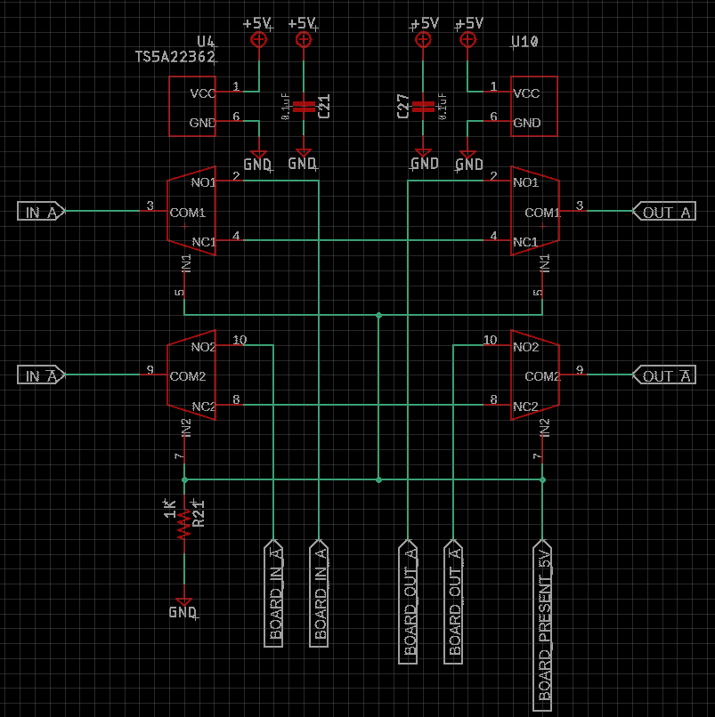
I'm trying to allow a user to plug and unplug a series-connected differential serial device in and out of the circuit on the fly.

When the device is plugged in the "Board Device Present" is pulled to 5V by an externally supplied 5V, at which time the switch routes the serial lines to and out of the board.  When not connected, the switch is supposed to bypass the board.

This works for a few mate cycles, but after a few mating cycles, the switches no longer respond to the Board Present 5V going to the IN1/In2 lines.

Any suggestions?

  • It doesn't look like the schematic came through, trying again.

  • Hi Kinsey,

    Based on the schematic there is nothing wrong with how it is wired.

    That being said, to clarify, have you had multiple failures? 

    Also do you have an Oscilloscope shots of IN1/IN2 signals during a mating cycle, specifically when they are connected together and also when they are separated? 

    My guesses at this point either has to do with the bus voltage of IN1/IN2 not getting up to the HIGH level minimum threshold (2.4V at VCC = 5V), or during the mating process some larger than expected voltage transient occurs during the mating process, or occurred during an mating process for a single board depending on the setup. However, I am not completely if either of those are the issues, those just look like the most probable explnations.

    Please let me know if you have/can share more information so I can further assist you in finding the problem.

    Best,

    Parker Dodson 

  • This has happened on multiple cards, each card has 12 pairs of switches (24 chips).  I've looked at the signals with a scope but I haven't scoped the mating event (good idea) and in some cases, NC is always connected and in other cases, NO is connected regardless of the state of IN1/IN2. It works a couple of matings then freezes in one state or the other.  The IN voltage is good.  I suspect transients coming from the external board so my next iteration optically isolates that signal.

    I was just looking for confirmation that I'm not doing something blatantly wrong.  I'll let you know the results of the optically isolated signal.

    Kinsey

  • Hi Kinsey,

    I am just checking if you have been able to get the information about voltages during the mating process?

    Best,

    Parker Dodson

  • The mating process looks pretty benign.  However, the de-mate sometimes presents voltages of between 8-10 VDC and up to 15V.  I'm waiting on some boards that have optical isolation in them so hopefully, that will correct the problem.

    Thanks for checking up!

    Kinsey

  • Opto-isolating the 5V select line appears to have solved the problem.  Everything now works as expected.  Thanks for your help!