- Ask a related questionWhat is a related question?A related question is a question created from another question. When the related question is created, it will be automatically linked to the original question.
Hi,
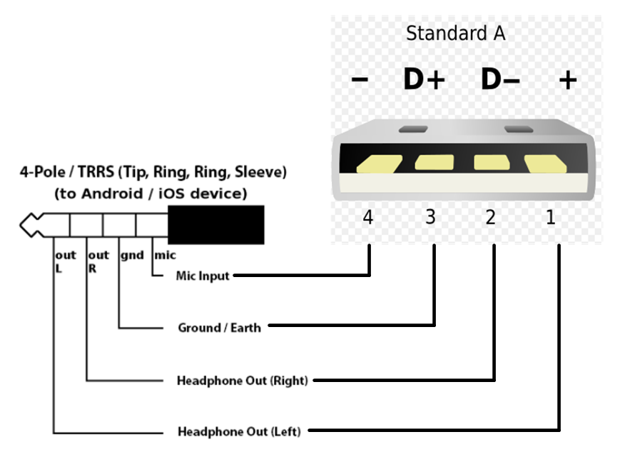
My customer are studying for RFQ which is relative to Headphone jack that support iOS & Android, support USB and apply CTIA conn rule.
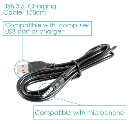
They want to support charge function through the audio jack too, that can support cable as below:
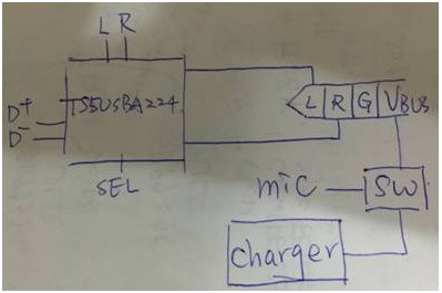
The concept is as below:
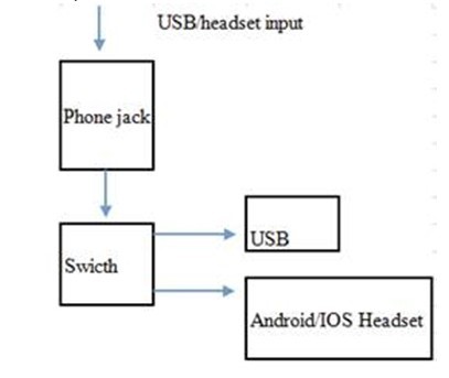
1. Do we have this kind design that can support switch for jack and USB?
2. How does the VBUS signal on 3.5mm connecter?
3. How can the switch identify the input source type?(adapter, usb)
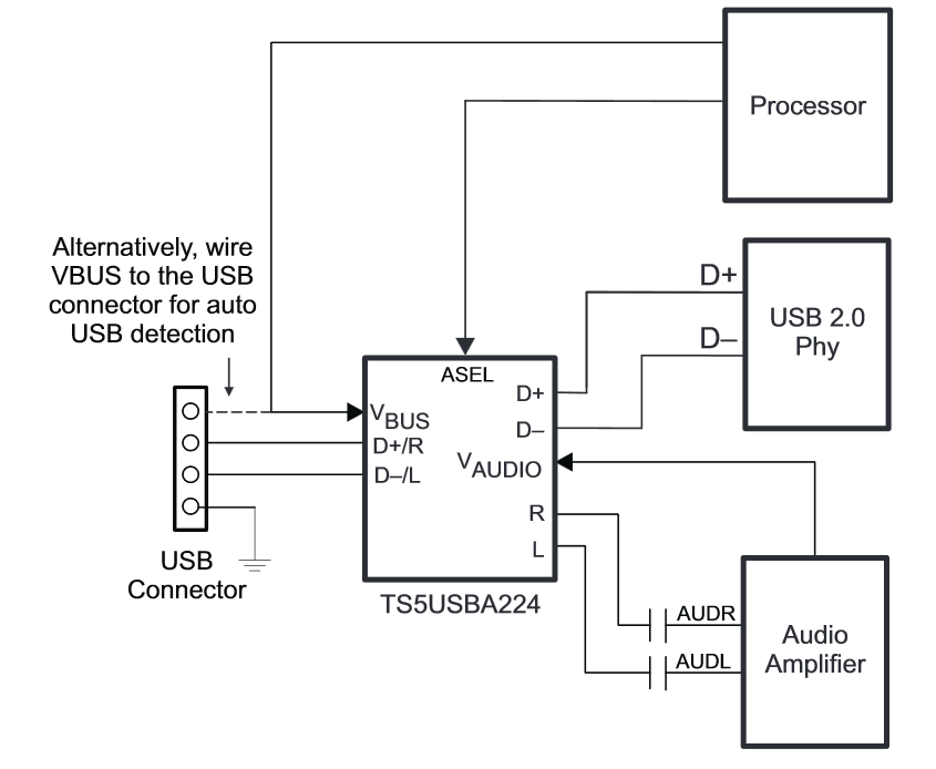
4. Does TS5USBA224 meet this requist? Or need to use TS3A22x family? please provide suitable solution.
Thanks
Daniel