This thread has been locked.

If you have a related question, please click the "Ask a related question" button in the top right corner. The newly created question will be automatically linked to this question.

SN74CBT3861: one application question for SN74CBT3861DBQR

Part Number: SN74CBT3861

Hi,

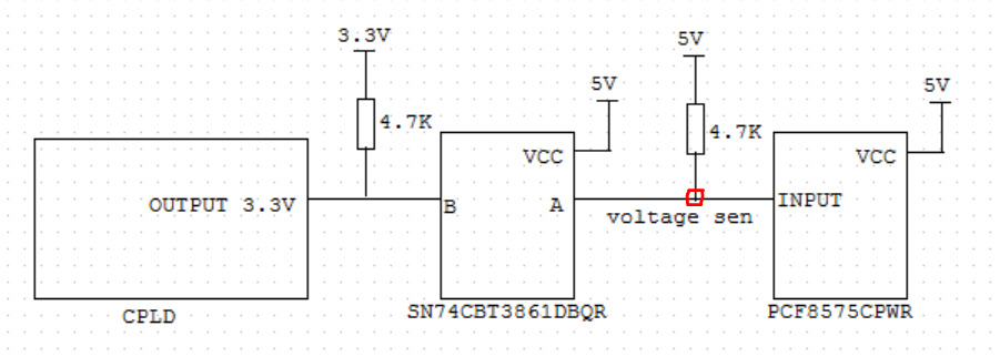
The following is our application for SN74CBT3861DBQR. Many boards have different voltages at the "voltage sensing" points, ranging from 3.4 to 4V. Why is there such a large voltage difference on different boards? could you give a comment?

Thanks.

  • Hey Oliver,

    Are you doing these measurements with the switch ON or OFF? 
    Is there a reason you have two pullups of different voltages? When the switch is on you'll have two supplies in parallel supplying different voltages.

    If this is somehow mitigated in your design and you're still seeing inconsistencies, could you switch two of the chips and see if the problem is dependent on the board or the switch? As in, if you have switch A and board A and switch B and board B, could you put switch A on board B and switch B on board A and see if you get the same measurements on the boards or the devices.

    Hope this helps,
    Rami 

  • Hi Rami,

    This is EE from JABIL.

    To answer your question:

    Are you doing these measurements with the switch ON or OFF? 

    Jabil: ON

    Is there a reason you have two pullups of different voltages?

    Jabil: Is there any problem with this? the right side is our test midplane, some design boards are used P5V pull-up.

    we have did the A-B-A switch test,  the voltage not follow the SN74CBT IC, but for some boards we measured that the voltage was 3.2V. After replacing it with a new SN74CBT IC, the voltage would be 3.6V. 

    SN:032028000351

    Before Rework U21

    After Rework U21

    3.2971

    3.6122(7FE3)

    3.2975

    3.6016(7FE3)

    3.2974

    3.6000(7FE3)

    SN:032028000498

    Before Rework

    After Rework

    3.3215

    3.8153(7FE3)

    3.3217

    3.8111(7FE3)

    3.3218

    3.8025(7FE3)

  • Hi Rami,

    This is EE from JABIL.

    To answer your question:

    Are you doing these measurements with the switch ON or OFF? 

    Jabil: ON
     

    we have did the A-B switch test, the voltage does not follow TI IC, but if it is replaced with new parts, the voltage may be higher:

    SN:032028000351

    Before Rework U21

    After Rework U21

    3.2971

    3.6122(7FE3)

    3.2975

    3.6016(7FE3)

    3.2974

    3.6000(7FE3)

    SN:032028000498

    Before Rework

    After Rework

    3.3215

    3.8153(7FE3)

    3.3217

    3.8111(7FE3)

    3.3218

    3.8025(7FE3)

  • Dannian,

    Do you get the proper pull up voltages when the switch is off?
    With nFET gates such as the SN74CBT3861 you'll find that the device has a hard time passing signals at the high side of the rail. This is documented in the technical article here in figure 7. You'll see that at 5Vcc the Ron increases significantly as Vi approaches the rail for the CBT family. Your 'rail' right now is 0-5V. This device has an allotted Vcc up to 5.5V's. You can also try, if possible in your design, increasing this value and seeing the effects. 

    Rami