This thread has been locked.

If you have a related question, please click the "Ask a related question" button in the top right corner. The newly created question will be automatically linked to this question.

CCS/MSP430FR5969: External signal capture. Problem with frequency

Part Number: MSP430FR5969

Tool/software: Code Composer Studio

Hello,

Days before I posted a doubt about trying to capture an external square wave signal using as an example "ta0_capture.c". but conecting in P1.3 an external signal instead of using the internal one. I achieved to capture the signal, but the increase of values of the timer (vector 'timerAcaptureValues') does not change if I increase the frecuency, neither the frequency of the external signal nor the frequency of the timer. What should I change or implement on the code, if I want that the Timer increment value changes if I modify the frequency of the external wave signal or the frequency of the timer?

Thank you,

**HERE IS THE CODE**

#include <msp430.h> 

#define NUMBER_TIMER_CAPTURES       20

volatile unsigned int timerAcaptureValues[NUMBER_TIMER_CAPTURES];
unsigned int timerAcapturePointer = 0;

int main(void)
{
    WDTCTL = WDTPW | WDTHOLD;	// Stop watchdog timer
	

    // Configure GPIO
     P1OUT &= ~0x01;                           // Clear P1.0 output
     P1DIR |= 0x01;

     P1SEL1 &= ~BIT3; 						   // Set P1.3 to input direction
     P1SEL0 |= BIT3;
     P1DIR &= ~BIT3;


     // Disable the GPIO power-on default high-impedance mode to activate
      // previously configured port settings
      PM5CTL0 &= ~LOCKLPM5;

      // Clock System Setup
      CSCTL0_H = CSKEY >> 8;                    // Unlock CS registers
      CSCTL1 = DCOFSEL_0;                       // Set DCO to 1MHz
      CSCTL2 = SELS__DCOCLK; 					// set SMCLK = DCO
      CSCTL3 = DIVS__1;						    // Set dividers
      CSCTL0_H = 0x00;                          // Lock CS module (use byte mode to upper byte)

      __delay_cycles(1000);                     // Allow clock system to settle

      // Timer0_A3 Setup
      TA1CCTL2 = CM_1 | CCIS_0 | SCS | CAP | CCIE;
                                                // Capture rising edge,
                                                // Use CCI2A=P1.3,
                                                // Synchronous capture,
                                                // Enable capture mode,
                                                // Enable capture interrupt

      TA1CTL = TASSEL__SMCLK | MC__CONTINUOUS;  // Use SMCLK as clock source,
                                                // Start timer in continuous mode

      __bis_SR_register(LPM0_bits | GIE);
      __no_operation();
    }

    // Timer1_A3 CC1-4, TA Interrupt Handler
    #if defined(__TI_COMPILER_VERSION__) || defined(__IAR_SYSTEMS_ICC__)
    #pragma vector = TIMER1_A1_VECTOR
    __interrupt void Timer1_A1_ISR(void)
    #elif defined(__GNUC__)
    void __attribute__ ((interrupt(TIMER1_A1_VECTOR))) Timer1_A1_ISR (void)
    #else
    #error Compiler not supported!
    #endif
    {
      switch (__even_in_range(TA1IV, TA1IV_TAIFG)) {
        case TA1IV_TA1CCR1:
          break;
        case TA1IV_TA1CCR2:
          timerAcaptureValues[timerAcapturePointer++] = TA1CCR2;

          if (timerAcapturePointer >= 20) {
            while (1) {
              P1OUT ^= 0x01;                    // Toggle P1.0 (LED)
              __delay_cycles(100000);
            }
          }
          break;
        case TA1IV_TA1IFG:
          break;
        default:
          break;
      }
    }

  • Hi Adrian,

    Do you means the value of timerAcaptureValues not change when you increase the input signal frequency? 

    How much the frequency of input signal?

    Could you provide some test data?

    Did you measure the SMCLK and input signal frequency?

    Best Regards

    Johnson

  • Hi Johnson,

    I mean that, for example: if I have an external square wave signal with a frequency of 10 kHz, and the frequency of the SMCLK is 1MHz (as the code) and I resume the code and then I suspend it, the values of the vector timerAcaptureValues are: 585, 1779, 2873, 4067, 6255, 7449, 8544, 9638, 10832, 11926, 13120, 14214, 15309, 16503, 17597, etc. That means that my timer has an increase value of aproximately 1000 every time that captures a rising edge from the signal of 10 kHz. I think that this is wrong because it should have an increase value of (1,000,000/10,000)=100. 

    Also, if I modify the value of the external signal or the frequency of the SMCLK, the values of timerAcaptureValues are not affected.

    What should I change on the code to resolve this problem?

    Thanks for your help,

  • Hi Adrian,

    In your program, this line need to modify :

          CSCTL2 = SELS__DCOCLK;                    // set SMCLK = DCO
          CSCTL3 = DIVS__1;                         // Set dividers

    Those need to changed to :

          CSCTL2 = SELA__VLOCLK | SELS__DCOCLK | SELM__DCOCLK;  // Set SMCLK = MCLK = DCO
                                                    // ACLK = VLOCLK
          CSCTL3 = DIVA__1 | DIVS__1 | DIVM__1;     // Set all dividers to 1

    Because you do not select the source of MCLK, and your code will set MCLK source to LFXTCLK/32768Hz(0x0000), Because the MCLK frequency to low cause this value is no longer the acquisition value when entering the interrupt, you can watch the COV(overflow) register be setting.

    Best Regards

    Johnson

  • Thank you, this resolved my problem about the frequency of the SMCLK. Is there any code line to implement if I want this?

    If I resume the code with 1MHz of SMCLK and 10 kHz of external signal, timerAcapturevalues has an increment of 100. But if I pause the program, modify the frequency of the external wave signal (for example, 5 kHz) and then I resume the program, timerAcapturevalues remains with the same increment of 100 and does not change to an increment of 200. This change only appears If I stop the project and then I build it and resume it again. Could be any way to make  timerAcapturevalues change pausing the code and changing the frequency? Or it can only be seen If I stop the program and I build the project again?

    This is the last question I have. Thank you so much and sorry for the inconvenience.

    Best regards,

  • Hi Adrian,

    I not found this issue you described when I test this demo.

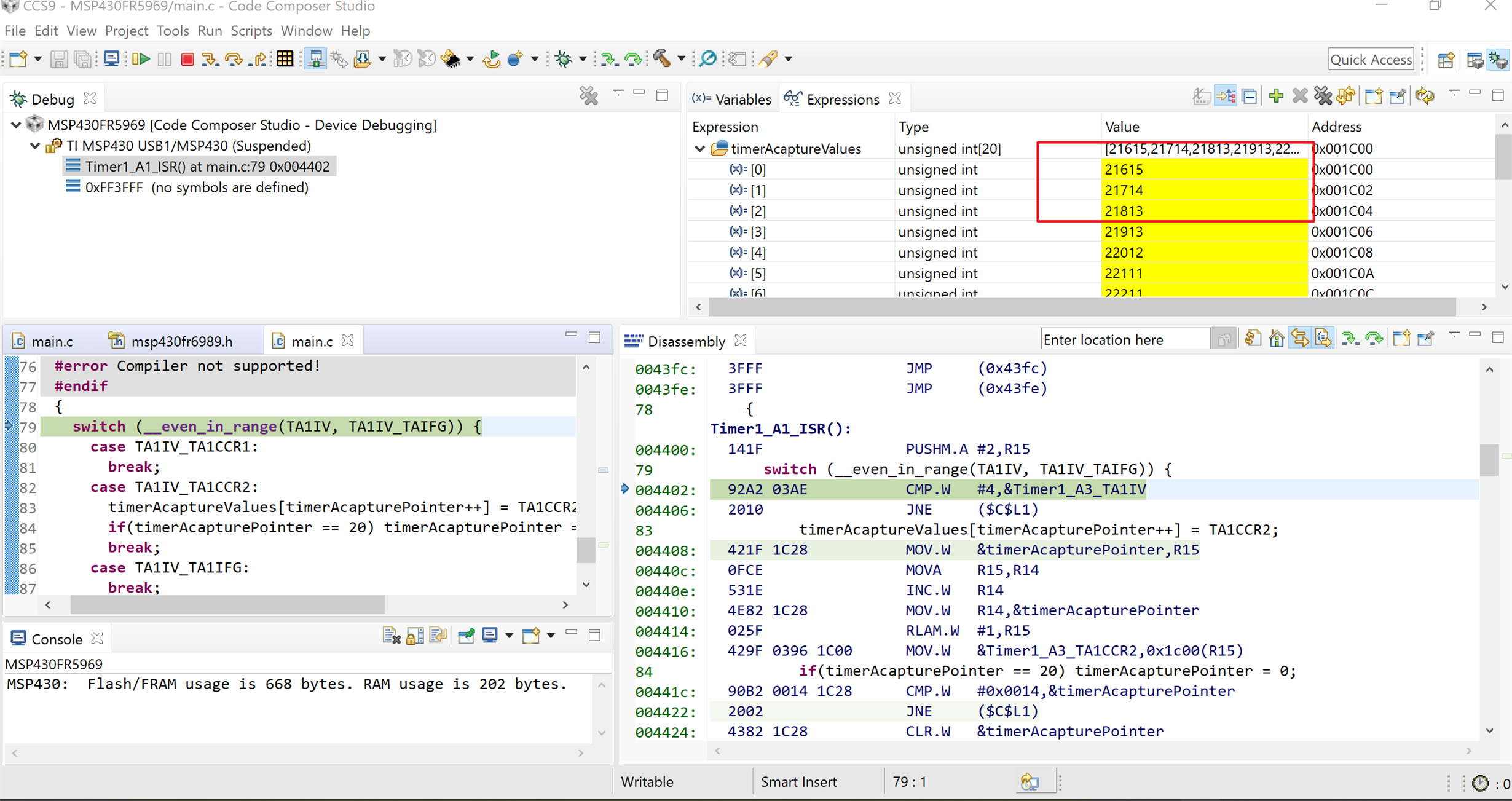
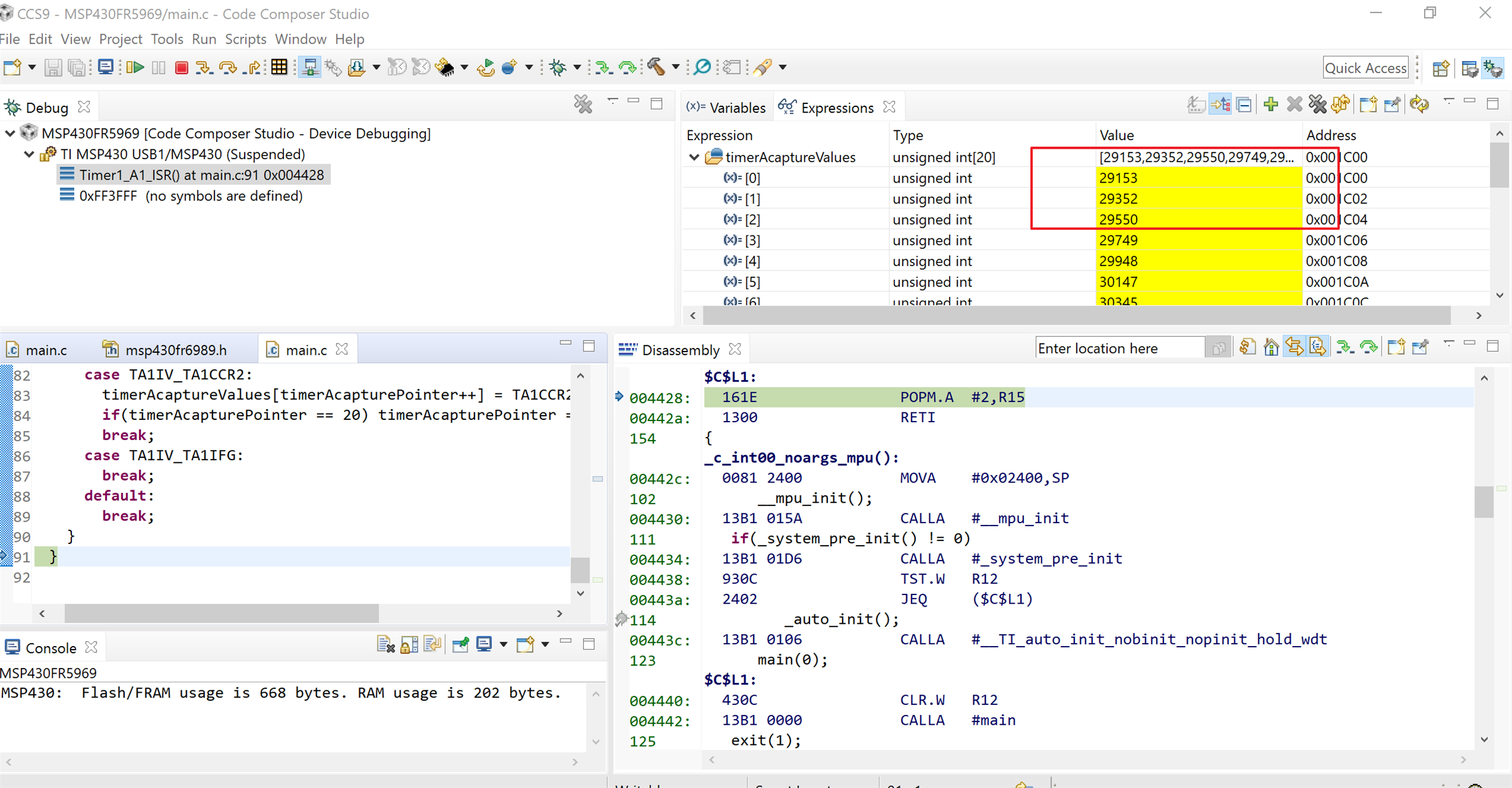
    Some test date as follow :

    Input signal frequency 10KHz:

    Input signal frequency 5KHz:

    My test code:

    #include <msp430.h>
    
    #define NUMBER_TIMER_CAPTURES       20
    
    volatile unsigned int timerAcaptureValues[NUMBER_TIMER_CAPTURES];
    unsigned int timerAcapturePointer = 0;
    
    int main(void)
    {
        WDTCTL = WDTPW | WDTHOLD;   // Stop watchdog timer
    
        // Configure GPIO
        P1SEL1 &= ~BIT3;                          // Set P1.3 to input direction
        P1SEL0 |= BIT3;
        P1DIR &= ~BIT3;
    
        P3DIR |= BIT4;
        P3SEL1 |= BIT4;                           // Output SMCLK
    
    
        // Disable the GPIO power-on default high-impedance mode to activate
        // previously configured port settings
        PM5CTL0 &= ~LOCKLPM5;
    
        // Clock System Setup
        CSCTL0_H = CSKEY >> 8;                    // Unlock CS registers
        CSCTL1 = DCOFSEL_0;                       // Set DCO to 1MHz
        CSCTL2 = SELA__VLOCLK | SELS__DCOCLK | SELM__DCOCLK;  // Set SMCLK = MCLK = DCO
                                                    // ACLK = VLOCLK
        CSCTL3 = DIVA__1 | DIVS__1 | DIVM__1;     // Set all dividers to 1
        CSCTL0_H = 0;                             // Lock CS module (use byte mode to upper byte)
    
        __delay_cycles(1000);                     // Allow clock system to settle
    
        // Timer0_A3 Setup
        TA1CCTL2 = CM_1 | CCIS_0 | SCS | CAP | CCIE;
                                                    // Capture rising edge,
                                                    // Use CCI2A=P1.3,
                                                    // Synchronous capture,
                                                    // Enable capture mode,
                                                    // Enable capture interrupt
    
        TA1CTL = TASSEL__SMCLK | MC__CONTINUOUS;  // Use SMCLK as clock source,
                                                    // Start timer in continuous mode
    
        __bis_SR_register(LPM0_bits | GIE);
        __no_operation();
    }
    
    // Timer1_A3 CC1-4, TA Interrupt Handler
    #if defined(__TI_COMPILER_VERSION__) || defined(__IAR_SYSTEMS_ICC__)
    #pragma vector = TIMER1_A1_VECTOR
    __interrupt void Timer1_A1_ISR(void)
    #elif defined(__GNUC__)
    void __attribute__ ((interrupt(TIMER1_A1_VECTOR))) Timer1_A1_ISR (void)
    #else
    #error Compiler not supported!
    #endif
    {
      switch (__even_in_range(TA1IV, TA1IV_TAIFG))
      {
        case TA1IV_TA1CCR1:
          break;
        case TA1IV_TA1CCR2:
          timerAcaptureValues[timerAcapturePointer++] = TA1CCR2;
          if(timerAcapturePointer == 20) timerAcapturePointer = 0;
          break;
        case TA1IV_TA1IFG:
          break;
        default:
          break;
      }
    }
    

    Best Regards

    Johnson