Other Parts Discussed in Thread: ADS7945
Tool/software: Code Composer Studio
Hello, TI's Engineer,
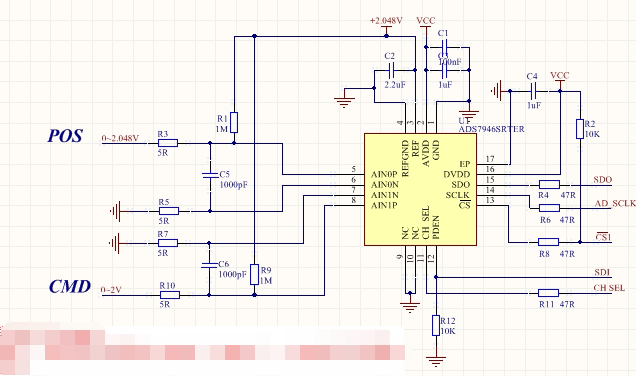
Problem description reference voltage is 2.048v
Demand: two signal inputs, POS signal range 0-2.048v (VREF); CMD signal range 0-2v: all DC signals.
Problem 1: when ads7946 is used for sampling, when the CMD voltage is VREF / 2, the transcoding value reaches the maximum value of 16384, and VREF / 2 ~ 2V is cycled again. This phenomenon is inconsistent with the introduction of chip manual
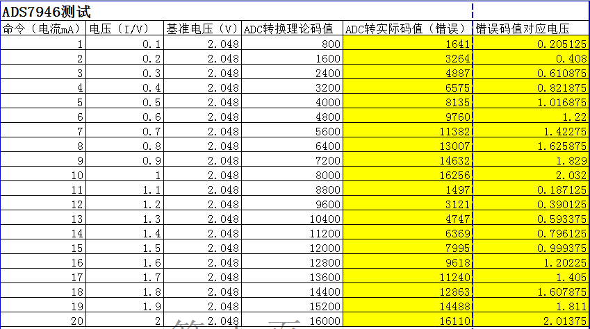
See attachment for test record
When the same circuit is replaced by ads7945, the corresponding conversion code value of 0-vref voltage is 0 ~ - 16384, which is not consistent with the ads7945 described in the manual.
Through the test phenomenon, it is felt that the introduction of ads7945 and ads7946 manuals is just opposite to the actual chip model
The software package here is written according to ads7945 / 7946 on the official website, because these two models are universal, but 7945 is differential, and 7946 is single ended. It is always suspected that there is a problem in software programming. Please give your engineering advice. I also attach the software code. Please give your guidance. If the description is not clear enough, please put forward my supplement below
This is the software code
unsigned int getdataADS7945(unsigned char GetCHSEL)
{
unsigned char t;
unsigned long hd;
unsigned long DataReadTemp;
hd = 0;
DataReadTemp = 0;
// GPIO_PinOutSet(gpioPortF, 3); //不掉电...
GPIO_PinOutClear(gpioPortF, 3);
if(GetCHSEL == 1)
{
GPIO_PinOutClear(gpioPortF, 2); //选择CH1...
}
else
{
GPIO_PinOutSet(gpioPortF, 2);
}
GPIO_PinOutClear(gpioPortF, 4); //CS脚拉低...
// GPIO_PinOutClear(gpioPortF, 5);
for(t=0;t<32;t++)
{
GPIO_PinOutSet(gpioPortF, 5);
// Delay(10);
hd<<=1;
GPIO_PinOutClear(gpioPortF, 5);
// Delay(10);
DataReadTemp = GPIO_PinInGet(gpioPortE, 8);
hd|=DataReadTemp;
// Delay(10);
}
hd>>=2;
hd = hd & 0x03fff;
GPIO_PinOutSet(gpioPortF, 4); //CS脚拉高...
// GPIO_PinOutSet(gpioPortF, 5);
return hd;
}