This thread has been locked.

If you have a related question, please click the "Ask a related question" button in the top right corner. The newly created question will be automatically linked to this question.

UCD3138A: Unable to debug .Out file into the UCD3138A micro controller.

Part Number: UCD3138A
Other Parts Discussed in Thread: UCD3138, USB-TO-GPIO2

Tool/software:

Hi All,

Greetings !!!

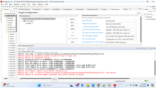
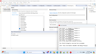
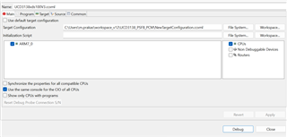
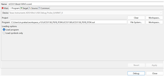
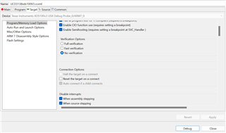
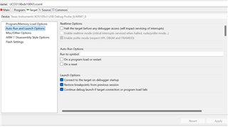
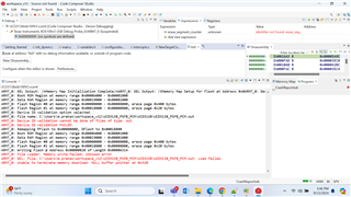
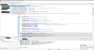
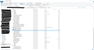
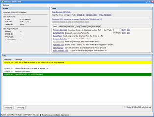
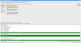
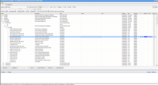
I have attached images of debugger options configured and error produced while debugging. could you please help me to get out of this issue.

  • Hello Prakash,

    Are you in the development/debug phase of your project with the UCD3138A? If so, then you should be debugging the UCD3138A via PMBus using the Fusion Studio GUI and the USB-TO-GPIO2 adapter. While the UCD3138A can be programmed via JTAG, that is only recommended for production firmware. It will be much easier to debug and develop with the UCD3138A via PMBus instead. 

    Please follow these instructions for debugging the UCD and using the memory map:

    UCD Memory Map Instructions

    I will be using the UCD3138 64-pin package with the UCD PFC Firmware as an example. I will also be changing the DPWM1A/B Cycle by Cycle (CBC) current limit on and off with the memory map.

    Step 1: Install Fusion Studio GUI

    Download the Fusion Studio GUI. When you download Fusion Studio GUI, you will have 3 programs that are installed: Fusion Studio Online, Fusion Design Offline and UCD3xxx Device GUI.

    Step 2: Build your UCD project to generate a .x0 file

    Use Code Composer Studio (CCS) to BUILD your UCD project. You do not use CCS to flash the UCD. Download the UCD PFC EVM firmware and open the project in CCS. On CCS, you can make any changes to the firmware that you would like. Once you are satisfied with your UCD project, click build and CCS will build the UCD project. In this example, we will be toggling the DPWM1A/B CBC enable bit in the memory map.

    Inherently as a UCD project, CCS will generate a .x0 file in your project build folder. When you click build in CCS for your UCD PFC firmware, a .x0 file will automatically generate. Make sure to select the correct UCD target in the build dropdown.

    Step 3: Connect to the UCD3138 using the UCD3xxx Device GUI

    Once you have the .x0 file generated, you will open Fusion Studio UCD3xxx Device GUI. Connect the UCD3138 control card with your computer via the USB-TO-GPIO2 adapter. The USB-TO-GPIO2 adapter communicates via PMBus, not JTAG. Click "Scan Device in ROM Mode" in the GUI. A green "Found ROM..." message should show up in the log. If not, then there is either something wrong with your adapter or your UCD chip. 


    Step 4: Flash firmware onto UCD

    Now that your UCD chip is detected in ROM mode, click on "Firmware Download". Navigate to the folder where your .x0 file has been generated and select the .x0 file. Click "Download". The PFC firmware will have successfully flashed onto your UCD3138 when the green "Found PFC SinglePhase Shunt Firmware..." message shows up. The firmware is now flashed onto your UCD chip and is ready to be used.

    Step 5: Open the memory map and load the correct .pp file

    In the main UCD3xxx Device GUI, click on the "Debug" tab and click on "Memory Debugger". The memory map will open. The memory map uses .pp files to monitor and change variables real-time. To load the .pp files, click File --> Change Map. Navigate to the folder that contains the generated .pp files. Click "Ok" and the correct memory map will load.


    Step 6: Monitor values with the memory map

    You can now use the memory map to monitor values real-time. As shown in step 2, the CBC enable bit is Dpwm1Regs.DPWMCTRL0.bit.CBC_PWM_AB_EN. So, this bit will be located in DPWM1Regs --> DPWMCTRL0 --> bit --> Bit Fields --> CBC_PWM_AB_EN[20:20]. You can also search or filter for specific registers with the top search bar.

    Click the "Refresh" button on the right to update all the registers. You can also automatically refresh the register values with the "Start Polling" feature on the upper left. You can change how often the registers refresh and which registers will be refreshed.

    Step 7: Change values with the memory map

    You can also use the memory map to change values real-time. In the "Value" column, the register will change from a 1 to a 0. Click "Write" to write the changes to the UCD. Any affected registers will be highlighted in red. After the value is successfully written, the affected registers will be highlighted in green with their new value.


    You can automatically write values to the registers using the "AutoWr" feature on the right. You can add specific registers to a watch list by clicking on the star next to each register. 

    Step 8: Use the Fusion Studio Online GUI

    The Fusion Studio Online is the GUI that allows you to change the loop compensation and other parameters real-time while your UCD is running on hardware. You will need to keep the UCD connected to your computer via the USB-TO-GPIO2 adapter while your UCD3138 is controlling an EVM. The Fusion Studio Online GUI uses the same method of changing registers with the .pp files like the memory map. Fusion Studio Offline is used when you do not have a UCD connected and allows you to view example UCD projects.

    Step 9: Use JTAG to flash production firmware

    Once you are satisfied with your firmware, you can then use JTAG and an XDS110 adapter to flash the final production firmware onto your UCD. This step should only be taken when your firmware is fully tested and will go into an end product. You do not need to use JTAG for debug and testing purposes. 

    You can view more information about the XDS110 and ARM/JTAG pinouts here.

    Regards,

    Jonathan Wong