This thread has been locked.

If you have a related question, please click the "Ask a related question" button in the top right corner. The newly created question will be automatically linked to this question.

CCS/SMJ320F2812: Why xrs stuck to 0.14V on SMJ320F2812, with the error 1137 the device is held in reset

Part Number: SMJ320F2812
Other Parts Discussed in Thread: TMS320F2812

Tool/software: Code Composer Studio

Hello everyone, I just change my design to SMJ320F2812.

My design used to work well on TMS320F2812.

Now I met several serious problems.

1, The XRS pin stucks to 0.14V.  the watchdog does it? I check the manual, only watchdog can do this. I check the 1.8V,3.3V, all goes well.

2,Whether or not SMJ320F2812 share the same GEL file with TMS320F2812, I think they belongs to the same family.

Thank for your attention.

the log as below:

C28xx: Failed Software Reset: (Error -1137 @ 0x0) Device is held in reset. Take the device out of reset, and retry the operation. (Release 5.0.429.0) 
C28xx: Trouble Reading PC Register: (Error -1137 @ 0x0) Device is held in reset. Take the device out of reset, and retry the operation. (Release 5.0.429.0) 
C28xx: Trouble Reading Register ST1: (Error -1137 @ 0x6) Device is held in reset. Take the device out of reset, and retry the operation. (Release 5.0.429.0) 
C28xx: GEL: Error while executing OnReset(1): Target failed to read the register ST1.

  • 1. The WD (if enabled and not serviced) will reset the device by driving the -XRS pin low for a 512 XCLKIN clock cycles. The XRS pin will not be "stuck" at 0.14v. What you are seeing is unlikely becuase of the WD.

    2. Functionally, both part numbers are identical, so yes, they belong to the same family.

    Since the package is different, it is evident you have redesigned the board. Please compare the schematics of the old and new boards to look for differences. Without looking at the schematics, I cannot provide further help. At the very least, I need to look at the circuitry connected to -XRS pin.
  • Dear Hareesh:

    The attached pdf is the schematic. And DSPRST is connected with RST.

    I will check the differences today.

    Is there possible the chip is partially damaged and the xclkout pin works well?

    Thank you!

    原理图.pdf

  • Can you please provide an oscilloscope capture of the -XRS, XCLKIN & XCLKOUT pins? Is it possible that the MAX706 pin is misbehaving and holding -XRS low? Have you seen this behavior on more than one board? I am wondering if this is a design issue or an isolated failure in one board?

  • Dear Hareesh:

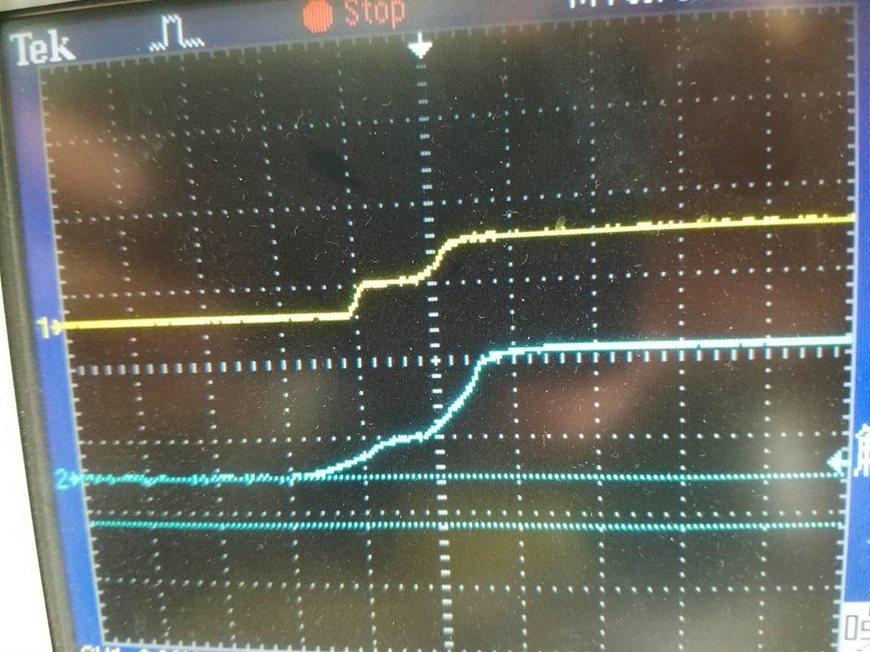
    I test 3.3V and1.8V voltage in the pic.

    yellow is 1.8V and blue line is 3.3V

    The bule line rise up to 2.5V with yellow line rising up 1.8V at the same time.

    While xrs remains low all the time.

    The same curcuits work well in the TMS320F2812.

    Thank you.

  • You have not answered my questions below:


    1. Can you please provide an oscilloscope capture of the -XRS, XCLKIN & XCLKOUT pins?
    2. Is it possible that the MAX706 pin is misbehaving and holding -XRS low?
    3. Have you seen this behavior on more than one board? I am wondering if this is a design issue or an isolated failure in one board?

    Please answer them.


    Two more questions:


    4. Are there any components between pin 5 (-RST) of U11 and pin 156 (-XRS) of U13? I am asking this because the nets are different (RST Vs DSPRST).


    5. Can you isolate the -XRS pin from U11 and repeat the experiment?

  • Dear Hareesh:

    Thank you for your time. I will answer your question one by one.

    1.The sinal XCLKIN and XLCKOUT is quite well with 30MHZ and 64KHZ waveform。

    2.MAX706(U11) was removed when tesing.

    3.This design works well on TMS320F2812.But this board uses SMJ320F2812, that is  the only defference.

    4.XRS and RST is conneced together.

    5.Like i said, U11 was removed when testing.

    I have some experiences in circuit design, but SMJ320F2812 is totally new for me.Crazy!

    Thank you again!

  • Dear Hareesh, my problem is resolved. One chip on the board was damaged for no reason. It consumed 0.7A current when working and DSP
    seems like going to protect mode. The circuit has no problem if every chip was good.
    Thank you again!