This thread has been locked.

If you have a related question, please click the "Ask a related question" button in the top right corner. The newly created question will be automatically linked to this question.

CCS / ADS1119:I2C

Part Number: ADS1119
Other Parts Discussed in Thread: LAUNCHXL-F28379D

Tool/software: Code Composer Studio

Hello

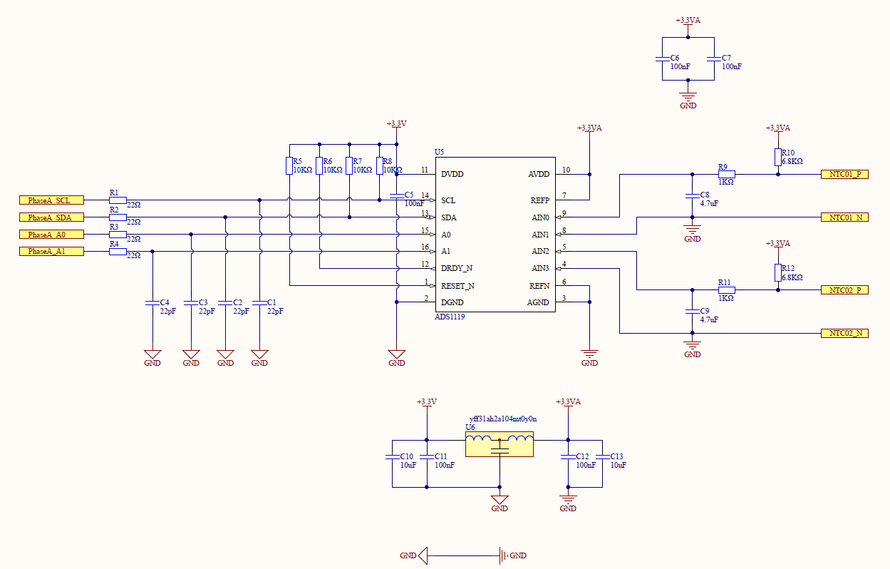
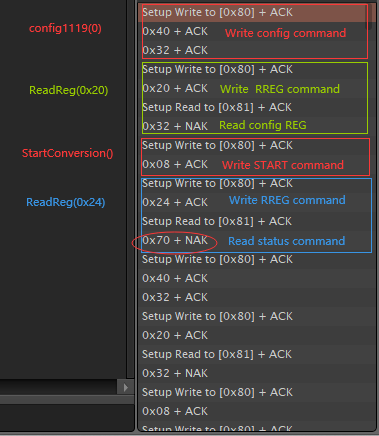
I encountered a problem when debugging ADS1119:

I2caRegs.I2CSTR.bit.XRDY would not be set to 1, (first time is 1, next and next time always be 0),causing the program to enter an infinite loop.Here is my code

main.c:

.....

while(1)

{

ReadData(0);
ReadData(1);
ReadData(2);
ReadData(3);

}

.......

I2C.c:

#include "F28x_Project.h"
#include "UserFuncs.h"
#include "CtrlParams.h"

#define CMD_Write 0x9C
#define CMD_Read 0x9D
#define CMD_CONF_REG 0x00
#define CMD_STATUS_REG 0x01

float32 data[4] = {0.0, 0.0, 0.0, 0.0};

//
// I2CA_Init - Initialize I2CA settings
//
void I2CA_Init(void)
{
I2caRegs.I2CMDR.bit.IRS =0;

I2caRegs.I2CSAR.all = 0x4E; // Slave address A1 = SCL, A0 = SDA

I2caRegs.I2CPSC.all = 6; // Prescaler - need 7-12 Mhz on module clk
I2caRegs.I2CCLKL = 10; // NOTE: must be non zero
I2caRegs.I2CCLKH = 5; // NOTE: must be non zero
I2caRegs.I2CIER.all = 0x24; // Enable SCD & ARDY interrupts
I2caRegs.I2CMDR.bit.IRS = 1; // Take I2C out of reset

}

Uint16 Config1119(Uint16 port)
{
Uint16 i, chn, config[2];
switch(port)
{
case 0: //channel 0
chn = 0x32;
break;
case 1: //channel 1
chn = 0x42;
break;
case 2: //channel 2
chn = 0x52;
break;
case 3: //channel 3
chn = 0x62;
break;
default:
break;
}
// config[0] = CMD_Write;
config[0] = CMD_CONF_REG;
config[1] = chn;
if (I2caRegs.I2CSTR.bit.BB == 1)
{
return I2C_BUS_BUSY_ERROR;
}
while(!I2C_xrdy());
I2caRegs.I2CSAR.all = 0x4E;
I2caRegs.I2CCNT = 2;
I2caRegs.I2CMDR.all = 0x6E20;
for (i=0; i<2; i++)
{
while(!I2C_xrdy());
I2caRegs.I2CDXR.all = config[i];
if (I2caRegs.I2CSTR.bit.NACK == 1)
return I2C_BUS_BUSY_ERROR;
}
DELAY_US(3000);
return I2C_SUCCESS;
}
Uint16 StatusRegister(void)
{
//First frame
if (I2caRegs.I2CSTR.bit.BB == 1)
{
return I2C_BUS_BUSY_ERROR;
}
while(!I2C_xrdy());
I2caRegs.I2CSAR.all = 0x4E;
I2caRegs.I2CCNT = 1;
// I2caRegs.I2CDXR = CMD_Write;
I2caRegs.I2CMDR.all = 0x6E20;
if (I2caRegs.I2CSTR.bit.NACK == 1)
return I2C_BUS_BUSY_ERROR;

while(!I2C_xrdy());
//I2caRegs.I2CDXR.all = CMD_STATUS_REG;
I2caRegs.I2CDXR.all = 0x24; //RREG command
if (I2caRegs.I2CSTR.bit.NACK == 1)
return I2C_BUS_BUSY_ERROR;

//Second frame
if (I2caRegs.I2CSTR.bit.BB == 1)
{
return I2C_BUS_BUSY_ERROR;
}
while(!I2C_xrdy());
I2caRegs.I2CSAR.all = 0x4E;
I2caRegs.I2CCNT = 1;
I2caRegs.I2CMDR.all = 0x6C20;
if (I2caRegs.I2CSTR.bit.NACK == 1)
return I2C_BUS_BUSY_ERROR;
else
return I2caRegs.I2CDRR.all >> 7;

//return I2C_SUCCESS;
}
Uint16 ReadData(Uint16 port)
{
Uint16 i, temp[2] = {0, 0}, dt = 0;
if(I2C_SUCCESS == Config1119(port))
{
if(StatusRegister() == 0x01)
{
//First frame
while(!I2C_xrdy());
I2caRegs.I2CSAR.all = 0x4E;
I2caRegs.I2CCNT = 1;
I2caRegs.I2CMDR.all = 0x6E20;
if (I2caRegs.I2CSTR.bit.NACK == 1)
return I2C_BUS_BUSY_ERROR;
while(!I2C_xrdy());
I2caRegs.I2CDXR.all = 0x10; //RDATA command
if (I2caRegs.I2CSTR.bit.NACK == 1)
return I2C_BUS_BUSY_ERROR;


//Second frame
I2caRegs.I2CSAR.all = 0x4E;
I2caRegs.I2CCNT = 2;
I2caRegs.I2CMDR.all = 0x6C20;
if (I2caRegs.I2CSTR.bit.NACK == 1)
return I2C_BUS_BUSY_ERROR;
for(i=0; i<2; i++)
{
while(!I2C_rrdy());
temp[i] = I2caRegs.I2CDRR.all;
if (I2caRegs.I2CSTR.bit.NACK == 1)
return I2C_BUS_BUSY_ERROR;
}
}
}
dt = temp[0]<<8 | temp[1];
data[port] = dt*1.25/10000;
DELAY_US(500);
return I2C_SUCCESS;
}
Uint16 I2C_xrdy()
{
Uint16 t;
t = I2caRegs.I2CSTR.bit.XRDY;
return t;
}

Uint16 I2C_rrdy()
{
Uint16 t;
t = I2caRegs.I2CSTR.bit.RRDY;
return t;
}

  • Hi J C1,

    The first thing you need to do is to verify your communication with either a logic analyzer or an oscilloscope.  You need to make sure that you are not receiving a NACK. 

    I cannot verify the SCL frequency nor tell if there are the required pull-ups on the SDA and SCL I2C lines.  Seeing a schematic would be helpful as well as plots of the communication.  So can you send me this information?

    In your code I do not see the START/SYNC command that starts the conversion.  To make sure that your communication is working properly I would suggest doing something very simple first, like writing and reading the registers to make sure that you are communicating properly.  After you know the communication is working properly you can advance to more complicated steps in your code.

    Best regards,

    Bob B

  • Hi Bob B,

    Thank you for your suggestion.

    (1)I verify the communication using a logic analyzer ,The results are shown below

    And when debugging, I find that the I2C bus has been busy,  (I2caRegs.I2CSTR.bit.BB = 1)

    (2)

    Sorry,I am using LAUNCHXL-F28379D for testing, there is no  plots of the communication, only the schematic of the ADS1119 module, and the connection photos I took.

    The connection is as follows:

    The black and white wires connect A0 and A1 to GND, the slave address is 0x40; The red wire (GND) and the yellow wire (3.3V) provide the 3.3V voltage for the ADS1119; The blue wire is the SAD wire, which is connected to LAUNCHPAD J1pin10, green line is SCL line, connect to pin9.

    (3)Thank you for your reminder, I have re-added the START / SYNC command, and I am trying a simple read and write operation to verify  whether the communication is working properly. 

    //The GPIO configuration

    void I2CAGpio_Init(void)
    {
        EALLOW;
        GpioCtrlRegs.GPDPUD.bit.GPIO104 = 0;   // Enable pull-up for GPIO104 (SDAA)
        GpioCtrlRegs.GPDPUD.bit.GPIO105 = 0;    // Enable pull-up for GPIO105 (SCLA)
    
        GpioCtrlRegs.GPDQSEL1.bit.GPIO104 = 3;  // Asynch input GPIO104 (SDAA)
        GpioCtrlRegs.GPDQSEL1.bit.GPIO105 = 3;  // Asynch input GPIO105 (SCLA)
    
        GpioCtrlRegs.GPDGMUX1.bit.GPIO104 = 0;   // Configure GPIO104 for SDAA operation
        GpioCtrlRegs.GPDGMUX1.bit.GPIO105 = 0;   // Configure GPIO105 for SCLA operation
    
        GpioCtrlRegs.GPDMUX1.bit.GPIO104 = 1;   // Configure GPIO104 for SDAA operation
        GpioCtrlRegs.GPDMUX1.bit.GPIO105 = 1;   // Configure GPIO105 for SCLA operation
    
        EDIS;
    }

    #include "F28x_Project.h"
    #include "UserFuncs.h"
    #include "CtrlParams.h"
    
    //#define CMD_Write     0x9C
    //#define CMD_Read      0x9D
    
    #define CMD_Write     0x80
    #define CMD_Read      0x81
    #define CMD_START     0x08
    #define CMD_CONF_REG  0x00
    #define CMD_STATUS_REG 0x01
    
    float32 data[4] = {0.0, 0.0, 0.0, 0.0};
    
    //
    // I2CA_Init - Initialize I2CA settings
    //
    void I2CA_Init(void)
    {
    //    I2caRegs.I2CSAR = 0x4E;       // Slave address  A1 = SCL, A0 = SDA
        I2caRegs.I2CSAR = 0x40;       // Slave address  A1 = DGND, A0 = DGND
        I2caRegs.I2CPSC.all = 19;          // Prescaler - need 7-12 Mhz on module clk     Sysclk=200Mhz
        I2caRegs.I2CCLKL = 10;            // NOTE: must be non zero
        I2caRegs.I2CCLKH = 5;             // NOTE: must be non zero
        I2caRegs.I2CIER.all = 0x00;     // Disable SCD & ARDY interrupts
        I2caRegs.I2CMDR.all = 0x0020;     // Take I2C out of reset
                                                                 // Stop I2C when suspended
    }
    Uint16 Start(void)
    {
        if (I2caRegs.I2CSTR.bit.BB == 1)
        {
           return I2C_BUS_BUSY_ERROR;
        }
        while(!I2C_xrdy());
        I2caRegs.I2CSAR = 0x40;
        I2caRegs.I2CCNT = 1;
        I2caRegs.I2CMDR.all = 0x6E20;
    
        if (I2caRegs.I2CSTR.bit.NACK == 1)
            return   I2C_BUS_BUSY_ERROR;
    
        while(!I2C_xrdy());
        I2caRegs.I2CDXR = CMD_START;
        if (I2caRegs.I2CSTR.bit.NACK == 1)
            return    I2C_BUS_BUSY_ERROR;
    
        return I2C_SUCCESS;
    }
    
    Uint16 Config1119(Uint16 port)
    {
        Uint16 i, chn, config[2];
        switch(port)
        {
        case 0:     //channel 0
            chn = 0x32;
            break;
        case 1:     //channel 1
            chn = 0x42;
            break;
        case 2:     //channel 2
            chn = 0x52;
            break;
        case 3:     //channel 3
            chn = 0x62;
            break;
        default:
            break;
        }
    //    config[0] = CMD_Write;
        config[0] = CMD_CONF_REG;
        config[1] = chn;
       if (I2caRegs.I2CSTR.bit.BB == 1)
       {
          return I2C_BUS_BUSY_ERROR;
       }
       while(!I2C_xrdy());
       I2caRegs.I2CSAR = 0x40;
       I2caRegs.I2CCNT = 2;
       I2caRegs.I2CMDR.all = 0x6E20;
       for (i=0; i<2; i++)
       {
          while(!I2C_xrdy());
          //I2caRegs.I2CDXR.all = config[i];
          I2caRegs.I2CDXR = config[i];
          if (I2caRegs.I2CSTR.bit.NACK == 1)
              return    I2C_BUS_BUSY_ERROR;
       }
       DELAY_US(500);
       return I2C_SUCCESS;
    }
    Uint16 StatusRegister(void)
    {
        //First frame
       if (I2caRegs.I2CSTR.bit.BB == 1)
       {
          return I2C_BUS_BUSY_ERROR;
       }
       while(!I2C_xrdy());
       I2caRegs.I2CSAR = 0x40;
       I2caRegs.I2CCNT = 1;
    //   I2caRegs.I2CDXR = CMD_Write;
       I2caRegs.I2CMDR.all = 0x6E20;
       if (I2caRegs.I2CSTR.bit.NACK == 1)
           return   I2C_BUS_BUSY_ERROR;
    
       while(!I2C_xrdy());
       //I2caRegs.I2CDXR.all = CMD_STATUS_REG;
       I2caRegs.I2CDXR = 0x24; //RREG command
       if (I2caRegs.I2CSTR.bit.NACK == 1)
           return   I2C_BUS_BUSY_ERROR;
    
       //Second frame
       if (I2caRegs.I2CSTR.bit.BB == 1)
       {
          return I2C_BUS_BUSY_ERROR;
       }
       while(!I2C_xrdy());
       I2caRegs.I2CSAR = 0x40;
       I2caRegs.I2CCNT = 1;
       I2caRegs.I2CMDR.all = 0x6C20;
       if (I2caRegs.I2CSTR.bit.NACK == 1)
           return   I2C_BUS_BUSY_ERROR;
       else
           return  I2caRegs.I2CDRR >> 7;
    
       //return I2C_SUCCESS;
    }
    Uint16 ReadData(Uint16 port)
    {
       Uint16  i, temp[2] = {0, 0}, dt = 0;
       if(I2C_SUCCESS == Config1119(port))
       {
           if(StatusRegister() == 0x01)
           {
               if(Start() == I2C_SUCCESS)
               {
                   //First frame
                   while(!I2C_xrdy());
                   I2caRegs.I2CSAR = 0x40;
                   I2caRegs.I2CCNT = 1;
                   I2caRegs.I2CMDR.all = 0x6E20;
                   if (I2caRegs.I2CSTR.bit.NACK == 1)
                       return  I2C_BUS_BUSY_ERROR;
                   while(!I2C_xrdy());
                   I2caRegs.I2CDXR = 0x10; //RDATA command
                   if (I2caRegs.I2CSTR.bit.NACK == 1)
                       return   I2C_BUS_BUSY_ERROR;
    
    
                   //Second frame
                   I2caRegs.I2CSAR = 0x40;
                   I2caRegs.I2CCNT = 2;
                   I2caRegs.I2CMDR.all = 0x6C20;
                   if (I2caRegs.I2CSTR.bit.NACK == 1)
                       return  I2C_BUS_BUSY_ERROR;
                   for(i=0; i<2; i++)
                   {
                       while(!I2C_rrdy());
                       temp[i] = I2caRegs.I2CDRR;
                       if (I2caRegs.I2CSTR.bit.NACK == 1)
                           return    I2C_BUS_BUSY_ERROR;
                   }
               }
           }
       }
       dt = temp[0]<<8 | temp[1];
       data[port] = dt*1.25/10000;
       DELAY_US(500);
       return I2C_SUCCESS;
    }
    Uint16  I2C_xrdy()
    {
        Uint16  t;
        t = I2caRegs.I2CSTR.bit.XRDY;
        return t;
    }
    
    Uint16  I2C_rrdy()
    {
        Uint16  t;
        t = I2caRegs.I2CSTR.bit.RRDY;
        return t;
    }
    

    Best regards,

    J C1

  • Hi J C1,

    The first two images did not show up in the post.  Can you try sending them again?

    In your schematic I see that you are using 10k pull-up resistors on SDA and SCL and you also have 22pF capacitors on these lines.  Capacitance can be a real problem when using I2C so I would recommend removing C1 and C2.  I would also recommend lowering the resistors to 2.7k for R7 and R8.

    I don't have a lot of experience with C2000 devices, so as you are using a register based control it is a little difficult for me to follow.  I really need to see examples of your communication with respect to reading and writing to the ADS1119.  This would need to be in the form of oscilloscope or logic analyzer plots.

    I did notice the following defines:

    #define CMD_Write     0x80
    #define CMD_Read      0x81
    To write to the ADS1119 the WREG command is 0x40 (Table 7 on page 25 of the ADS1119 datasheet) and the read register command is either 0x20 (for reading register 0) or 0x24 (for reading register 1).  In the function Config1119() you are setting the first array element to CMD_CONF_REG which you have defined as 0x00, but should be 0x40 (register write command) followed by the configuration register data (the next element in the array).
    Best regards,
    Bob B
  • Hi Bob B,

    According to your suggestion, I modified the code. After testing, I found that the problem is the Write-function.

    When I write one byte, the program runs normally. The following is the result of the logic analyzer test: Sending START / SYNC command to ADS1119.

    But when I send two bytes, there is a problem, the bus status becomes busy and NACK is received. The following is the result of writing to the configuration register:The ACK can be received after the first byte(0x80) is written , but the next byte(0x32) without ACK and the bus enters a busy state.

    Uint16 Write1(void)
    {
        if (I2caRegs.I2CSTR.bit.BB == 1)
        {
           return I2C_BUS_BUSY_ERROR;
        }
        I2caRegs.I2CSAR = 0x40;     //SLAVE ADDRESS
        I2caRegs.I2CCNT = 1;
        I2caRegs.I2CDXR = 0x08;     //START/SYNC  Command
        if (I2caRegs.I2CSTR.bit.NACK == 1)
            return   I2C_BUS_BUSY_ERROR;
        I2caRegs.I2CMDR.all = 0x6E20;
        return I2C_SUCCESS;
    }
    
    Uint16 Write2(void)
    {
        Uint16 i, config[2];
        if (I2caRegs.I2CSTR.bit.BB == 1)
        {
           return I2C_BUS_BUSY_ERROR;
        }
        config[0] = 0x40;
        config[1] = 0x32;            //channel 0
        I2caRegs.I2CSAR = 0x40;     //SLAVE ADDRESS
        I2caRegs.I2CCNT = 2;
        for (i=0; i<2; i++)
        {
            I2caRegs.I2CDXR = config[i];
            DELAY_US(500);
    //        while(!I2caRegs.I2CSTR.bit.XRDY)
            if (I2caRegs.I2CSTR.bit.NACK == 1)
                return    I2C_BUS_BUSY_ERROR;
        }
        I2caRegs.I2CMDR.all = 0x6E20;
        return I2C_SUCCESS;
    }

    Best regards,

    J C1

  • Hello Bob B,

    Sorry to bother you again.I have another question: Do I need to specify registers when START / SYNC command is written to ADS1119?
    If not needed, will DRDY be automatically set to 1 after a START / SYNC command successful write?

    Uint16 Start(void)
    {
        if (I2caRegs.I2CSTR.bit.BB == 1)
        {
           return I2C_BUS_BUSY_ERROR;
        }
        I2caRegs.I2CSAR = 0x40;     //SLAVE ADDRESS
        I2caRegs.I2CCNT = 1;
        I2caRegs.I2CDXR = CMD_START; //0x08
        if (I2caRegs.I2CSTR.bit.NACK == 1)
            return   I2C_BUS_BUSY_ERROR;
        I2caRegs.I2CMDR.all = 0x6E20;
        return I2C_SUCCESS;
    }
    Uint16 StatusRegister(void)
    {
        if (I2caRegs.I2CSTR.bit.BB == 1)
        {
            return I2C_BUS_BUSY_ERROR;
        }
        I2caRegs.I2CSAR = 0x40;
        I2caRegs.I2CCNT = 1;
        I2caRegs.I2CDXR = 0x24; //RREG command       status
    //    I2caRegs.I2CDXR = 0x20;   //RREG command       config
        I2caRegs.I2CMDR.all = 0x6E20;
        if (I2caRegs.I2CSTR.bit.NACK == 1)
            return  I2C_BUS_BUSY_ERROR;
    
        if (I2caRegs.I2CSTR.bit.BB == 1)
        {
            return I2C_BUS_BUSY_ERROR;
        }
        I2caRegs.I2CSAR = 0x40;
        I2caRegs.I2CCNT = 1;
        I2caRegs.I2CMDR.all = 0x6C20;
        if (I2caRegs.I2CSTR.bit.NACK == 1)
             return  I2C_BUS_BUSY_ERROR;
        return  I2caRegs.I2CDRR;
    }
    Uint16 ReadData(Uint16 port)
    {
        Uint16  i;
        if(I2C_SUCCESS == Start())
        {
            if(0x80 == (StatusRegister() & 0x80))
            {
                //First frame
                if (I2caRegs.I2CSTR.bit.BB == 1)
                {
                    return I2C_BUS_BUSY_ERROR;
                }
                I2caRegs.I2CSAR = 0x40;
                I2caRegs.I2CCNT = 1;
                I2caRegs.I2CMDR.all = 0x6E20;
                I2caRegs.I2CDXR = 0x10; //RDATA command
                if (I2caRegs.I2CSTR.bit.NACK == 1)
                    return  I2C_BUS_BUSY_ERROR;
    
                //Second frame
                if (I2caRegs.I2CSTR.bit.BB == 1)
                {
                    return I2C_BUS_BUSY_ERROR;
                }
                I2caRegs.I2CSAR = 0x40;
                I2caRegs.I2CCNT = 2;
                I2caRegs.I2CMDR.all = 0x6C20;
                for(i=0; i<2; i++)
                {
                    temp[i] = I2caRegs.I2CDRR;
                    if (I2caRegs.I2CSTR.bit.NACK == 1)
                        return    I2C_BUS_BUSY_ERROR;
                }
            }
        }
        return I2C_SUCCESS;
    
    }

    The above is my code, although the START command is used, but the return result is 0x00, the data conversion is not successful.

  • Hi J C1,

    In your Write2() function it is showing something different than what it is shown in the logic analyzer plots.  What you should see is 3 bytes following I2C Start condition.  The first byte is the address with a write (0x80).  The second byte should show the WREG command (0x40) followed by the 3rd byte which should be the data (0x32).  This should be one continuous transfer with no breaks in the transmission (repeated Start is ok, but a Stop condition ends the communication at that point).

    The sequence shown in the plots is showing what happens to be each byte transferred separately. The reason you see a NACK is there is no 0x32 command so the ADS1119 doesn't know what to do with the data.

    The same situation would be true for reading the data, but in this case you send the RDATA command as a write, and then you need to read 2 bytes as data.  The reading of data requires a sequence of three bytes.  The first would be 0x81 which is the address with a read.  The next to bytes would be reading the conversion data.  The two bytes need to be read continuously.  If a Stop condition occurs the RDATA command will cancel.

    I suspect that there is something missing in the way you are sequencing the data with respect to the register settings currently being used for the I2C sequences.  Even though you are setting the I2caRegs.I2CCNT = 2; it is only transmitting one byte at a time instead of in a 2 byte sequence.

    Best regards,

    Bob B

  • Hi J C1,

    The DRDY status bit does not behave in quite the same way as the DRDY pin.  The default setting for the DRDY bit is '0'.  When you send the START/SYNC command the bit will stay '0' until the conversion has completed and the data are available to be read and the DRDY bit is now '1'.  The bit will stay high until the conversion results are read.  Reading the conversion result will reset the DRDY bit back to '0'.

    As I stated in my previous post, the sequence of reading the register must also include the RREG command. I think part of your question is if you have to send the RREG command each time you attempt to read the DRDY status and the answer is yes.  The RREG command instructs the ADS1119 to place the contents of the register into the output buffer to be read.  Once the buffer is read it becomes empty.  

    As I only see part of the transaction I cannot tell if the command was executed properly.  If you want to attach the Saleae file I can look at the contents more closely.

    Best regards,

    Bob B

  • Hi Bob B,

    With your help, the communication has been successful, but the DRDY bit I read is always 0 when reading the data, is my method wrong?

    Uint16 Start(void)
    {
        if (I2caRegs.I2CSTR.bit.BB == 1)
        {
           return I2C_BUS_BUSY_ERROR;
        }
        I2caRegs.I2CSAR = 0x40;     //SLAVE ADDRESS
        I2caRegs.I2CCNT = 1;
        I2caRegs.I2CDXR = 0x08;
        if (I2caRegs.I2CSTR.bit.NACK == 1)
            return   I2C_BUS_BUSY_ERROR;
        I2caRegs.I2CMDR.all = 0x6E20;
        return I2C_SUCCESS;
    }
    Uint16 StatusRegister(void)
    {
        if (I2caRegs.I2CSTR.bit.BB == 1)
        {
            return I2C_BUS_BUSY_ERROR;
        }
        I2caRegs.I2CSAR = 0x40;
        I2caRegs.I2CCNT = 1;
        I2caRegs.I2CDXR = 0x24; //RREG command       status
        //I2caRegs.I2CDXR = 0x20;   //RREG command       config
        I2caRegs.I2CMDR.all = 0x6E20;
        if (I2caRegs.I2CSTR.bit.NACK == 1)
            return  I2C_BUS_BUSY_ERROR;
    
        I2caRegs.I2CSAR = 0x40;
        I2caRegs.I2CCNT = 1;
        I2caRegs.I2CMDR.all = 0x6C20;
    
        return  I2caRegs.I2CDRR;
    }
    Uint16 ReadData(Uint16 port)
    {
        Uint16 i;
        if(I2C_SUCCESS == Config1119(port))
        {
            if(I2C_SUCCESS == Start())
            {
                if(0x80 == (StatusRegister() & 0x80))        //The return value of the StatusRegister() function is always 0
                {
                    //
                    if (I2caRegs.I2CSTR.bit.BB == 1)
                    {
                        return I2C_BUS_BUSY_ERROR;
                    }
                    I2caRegs.I2CSAR = 0x40;
                    I2caRegs.I2CCNT = 1;
                    I2caRegs.I2CMDR.all = 0x6E20;
                    I2caRegs.I2CDXR = 0x10; //RDATA command
                    if (I2caRegs.I2CSTR.bit.NACK == 1)
                        return  I2C_BUS_BUSY_ERROR;
    
                    //
                    if (I2caRegs.I2CSTR.bit.BB == 1)
                    {
                        return I2C_BUS_BUSY_ERROR;
                    }
                    I2caRegs.I2CSAR = 0x40;
                    I2caRegs.I2CCNT = 2;
                    I2caRegs.I2CMDR.all = 0x6C20;
                    for(i=0; i<2; i++)
                    {
                        temp[i] = I2caRegs.I2CDRR;
                        if (I2caRegs.I2CSTR.bit.NACK == 1)
                            return    I2C_BUS_BUSY_ERROR;
                    }
                }
            }
        }
    
        return I2C_SUCCESS;
    
    }

  • Hi J C1,

    The code only calls the StatusRegister() function one time.  The ReadData() function reconfigures the mux each time it is called.  When the mux is changed the conversion will restart, so it appears that there is an endless loop where the conversion is never allowed to complete.

    On possible thing you could do is in the StatusRegister() function create a loop where you continuously read the register until the DRDY bit goes high, and then you break out of the loop and go back and read the the data.

    Best regards,

    Bob B

  • Hi Bob B,

    I try to create a loop at the end of the StatusRegister() function,but it become an endless loop.And then I test with a logic analyzer and find that the status register returned a value of 0x70,not 0x80.

    /***************main.c***************/
    //test code
    if(Config1119(0) == I2C_SUCCESS)
    {
        ReadReg(0X20);
    }
    DELAY_US(100);
    StartConversion();
    
    DELAY_US(100);
    ReadReg(0X24);
    /*************************************/


    Uint16 ReadReg(Uint16 RegAddr)
    {
    //    RREG command
    //    0x24       status
    //    0x20       config
        if (I2caRegs.I2CSTR.bit.BB == 1)
        {
            return I2C_BUS_BUSY_ERROR;
        }
        I2caRegs.I2CSAR = 0x40;
        I2caRegs.I2CCNT = 1;
        I2caRegs.I2CDXR = RegAddr;         //RREG command
        I2caRegs.I2CMDR.all = 0x6E20;
        if (I2caRegs.I2CSTR.bit.NACK == 1)
            return  I2C_BUS_BUSY_ERROR;
        DELAY_US(100);
    
        I2caRegs.I2CSAR = 0x40;
        I2caRegs.I2CCNT = 1;
        I2caRegs.I2CMDR.all = 0x6C20;
    //    while(!(I2caRegs.I2CDRR & 0x80 == 0x80));
        return  I2caRegs.I2CDRR;
    }
    Uint16 Config1119(Uint16 port)
    {
        Uint16 i, chn, config[2];
        switch(port)
        {
        case 0:     //channel 0
            chn = 0x32;
            break;
        case 1:     //channel 1
            chn = 0x42;
            break;
        case 2:     //channel 2
            chn = 0x52;
            break;
        case 3:     //channel 3
            chn = 0x62;
            break;
        default:
            break;
        }
        config[0] = 0x40;      //WREG command
        config[1] = chn;
       if (I2caRegs.I2CSTR.bit.BB == 1)
       {
          return I2C_BUS_BUSY_ERROR;
       }
       I2caRegs.I2CSAR = 0x40;
       I2caRegs.I2CCNT = 2;
       for (i=0; i<2; i++)
       {
           I2caRegs.I2CDXR = config[i];
           if (I2caRegs.I2CSTR.bit.NACK == 1)
               return    I2C_BUS_BUSY_ERROR;
       }
       I2caRegs.I2CMDR.all = 0x6E20;
       DELAY_US(100);
       return I2C_SUCCESS;
    }
    Uint16 StartConversion(void)
    {
        if (I2caRegs.I2CSTR.bit.BB == 1)
        {
           return I2C_BUS_BUSY_ERROR;
        }
        I2caRegs.I2CSAR = 0x40;     //SLAVE ADDRESS
        I2caRegs.I2CCNT = 1;
        I2caRegs.I2CDXR = 0x08;     //Start or restart conversions  command
        if (I2caRegs.I2CSTR.bit.NACK == 1)
            return   I2C_BUS_BUSY_ERROR;
        I2caRegs.I2CMDR.all = 0x6E20;
        DELAY_US(100);
        return I2C_SUCCESS;
    }

    Best regards,

    J C1

  • Hi Bob B,

    I find in the ADS1119 Technical Reference Manual that the conversion time takes at least 50ms.So I try adding a delay function and read the status register successfully(0xF0).

    Now I have two questions:

    (1)The purpose of creating a loop is also to delay, why the effect is completely different.

    (2)The result is always 0x7FFFF, is it where I have not configured yet?

    /**************main.c****************/           
     if(Config1119(0) == I2C_SUCCESS)
    {
        if(StartConversion() == I2C_SUCCESS)
        {
            DELAY_US(100000); 
            ReadReg(0X24);
            DELAY_US(100);
            ReadData();
        }
    }
    
    
    Uint16 Config1119(Uint16 port)
    {
        Uint16 i, chn, config[2];
        switch(port)
        {
        case 0:     //channel 0
            chn = 0x32;
            break;
        case 1:     //channel 1
            chn = 0x42;
            break;
        case 2:     //channel 2
            chn = 0x52;
            break;
        case 3:     //channel 3
            chn = 0x62;
            break;
        default:
            break;
        }
        config[0] = 0x40;      //WREG command
        config[1] = chn;
       if (I2caRegs.I2CSTR.bit.BB == 1)
       {
          return I2C_BUS_BUSY_ERROR;
       }
       I2caRegs.I2CSAR = 0x40;
       I2caRegs.I2CCNT = 2;
       for (i=0; i<2; i++)
       {
           I2caRegs.I2CDXR = config[i];
           if (I2caRegs.I2CSTR.bit.NACK == 1)
               return    I2C_BUS_BUSY_ERROR;
       }
       I2caRegs.I2CMDR.all = 0x6E20;
       DELAY_US(100);
       return I2C_SUCCESS;
    }
    
    Uint16 ReadReg(Uint16 RegAddr)
    {
    //    RREG command
    //    0x24       status
    //    0x20       config
        if (I2caRegs.I2CSTR.bit.BB == 1)
        {
            return I2C_BUS_BUSY_ERROR;
        }
        I2caRegs.I2CSAR = 0x40;
        I2caRegs.I2CCNT = 1;
        I2caRegs.I2CDXR = RegAddr;         //RREG command
        I2caRegs.I2CMDR.all = 0x6E20;
        if (I2caRegs.I2CSTR.bit.NACK == 1)
            return  I2C_BUS_BUSY_ERROR;
        DELAY_US(100);
    
        I2caRegs.I2CSAR = 0x40;
        I2caRegs.I2CCNT = 1;
        I2caRegs.I2CMDR.all = 0x6C20;
        //while(!(I2caRegs.I2CDRR & 0x80 == 0x80));
        return  I2caRegs.I2CDRR;
    }
    Uint16 StartConversion(void)
    {
        if (I2caRegs.I2CSTR.bit.BB == 1)
        {
           return I2C_BUS_BUSY_ERROR;
        }
        I2caRegs.I2CSAR = 0x40;     //SLAVE ADDRESS
        I2caRegs.I2CCNT = 1;
        I2caRegs.I2CDXR = 0x08;     //Start or restart conversions  command
        if (I2caRegs.I2CSTR.bit.NACK == 1)
            return   I2C_BUS_BUSY_ERROR;
        I2caRegs.I2CMDR.all = 0x6E20;
        DELAY_US(100);
        return I2C_SUCCESS;
    }
    
    Uint16 ReadData(void)
    {
        Uint16 i;
        //
        if (I2caRegs.I2CSTR.bit.BB == 1)
        {
            return I2C_BUS_BUSY_ERROR;
        }
    
        I2caRegs.I2CSAR = 0x40;
        I2caRegs.I2CCNT = 1;
        I2caRegs.I2CMDR.all = 0x6E20;
        I2caRegs.I2CDXR = 0x10; //RDATA command.
        if (I2caRegs.I2CSTR.bit.NACK == 1)
            return  I2C_BUS_BUSY_ERROR;
        DELAY_US(100);
        //
        I2caRegs.I2CSAR = 0x40;
        I2caRegs.I2CCNT = 2;
        I2caRegs.I2CMDR.all = 0x6C20;
        for(i=0; i<2; i++)
        {
            temp[i] = I2caRegs.I2CDRR;
        }
        return I2C_SUCCESS;
    }
    

    Best regards,

    J C1

  • Hi Bob B,

    I have solved all the problems, thank you for your guidance during this time, thank you very much!

    Best regards,

    J C1