This thread has been locked.

If you have a related question, please click the "Ask a related question" button in the top right corner. The newly created question will be automatically linked to this question.

OPA656 Spice model

Other Parts Discussed in Thread: OPA827, TINA-TI, OPA656

Hello,

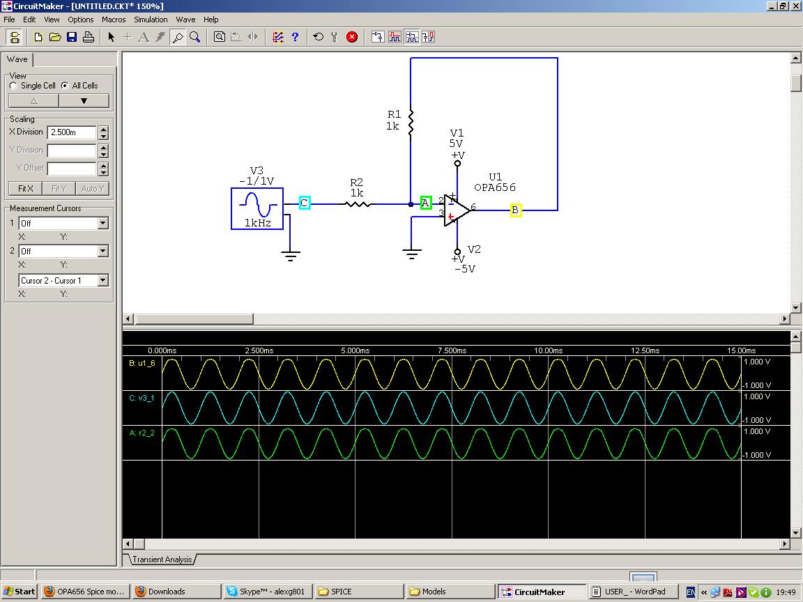
   I tried to add the Spice model of OPA656 to the simulation program CircuitMaker 2000. Unfortunately for the simulation process I got the following:

Unrecognized parameter [ALPHA] in JFET model - ignored
Unrecognized parameter [VK] in JFET model - ignored
Unrecognized parameter [BETATCE] in JFET model - ignored
Unrecognized parameter [vtotc] in JFET model - ignored

As a result the simulatation cannot be finished.

Please, advice how to avoid this problem. May be there exists another spice model?

The model of OPA827 was accepted OK and I simulated my design successfully.

Regards,
Alex

  • Alex,

    Thanks for the inquiry. I am a modeling engineer in the WEBENCH Design Center.
    This message suggests to alternatives that I hope will fix your problem:

    Alternative 1: TINA-TI
    If your priorities allow, please consider TINA-TI, our free simulator available at: http://www.ti.com/tool/tina-ti
    The OPA656 is in the internal TINA-TI Spice Macro libraries and can be placed in a schematic with a drag-and-drop from the library menus.
    Many TI analog components have TINA macros published on their product folders at ti.com, was well as reference circuits that can be downloaded or opened directly by TINA-TI from their URLs.

    Alternative 2: Modified OPA656 model
    The errors you showed in your message are parameters associated with the macro's JFET model.
    We validate our models in Pspice and TINA-TI, so I checked the models description in the Pspice documentation.
    The parameters ALPHA and VK are the JFET ionization coefficient and ionization knee voltage.
    The BETATCE and VTOTC are the temp coefficients for beta and the VTO respectively.
    As an experiment, the results of some Pspice AC & noise sims were compared with the the model as it is published, and with the four JFET parameters commented out. The test circuit was the published reference circuit with a gain of +2.
    The results with the four JET parameters removed give a BW that is 15% higher, and noise that is ~5% lower than the nominal model.
    I do not know if the variations are acceptable for your application, but I have attached a modified model netlist to this thread.
    It has the four parameters commented out. PLease try the model in your silumlator and let me know if you still see the errors.

    The differences in simulator and model behavior  can occur because of syntax, computational and convergence algorithms, and a host of other issues.
    Unfortunately we do not have access to Circuitmaker, so we cannot do a more thorough evalutaion of our model in that simulator.

    Please let me know if you have any questions or concerns.

    Regards,
    John

    OPA656_mod.LIB
  • Hello John,

       Thanks a lot for your reply and an explanation concerning the model.

    Now Circuit Maker accepts your modified model and the simulation process is functioning.

    However the result of the simulation is wrong. I apply the the where you can that inverting amplifier does not do

    its work. Your OPA827 model is working properly in the same scheme. What can be?

    I would not go to TINA so as all my developments are done in Circuit Maker 2000, I successfully work in this

    program for 12 years.Could you help?

    Regards,

    Alex

  • Alex,

    I have a few questions about your circuit:
    1. Both power supplies have a terminal named "V+". Should +5V and -5V perhaps have different terminal names?
    2. Can you check the current drain of the macromodel?  
         The model may not have power and the output waveform may be from the R1/R2 signal path from the source to the output node.
         Another way to test this is to put a 2k load resistor on the output. If the output swing drops by half, the model is probably not powered up. 
         The modified model with your circuit copied into  in Pspice (+5V/-5V supplies) has 11mA of current drain.
    3. The OPA656 is a 5-pin model and it looks like the output node has a pin number of '6'. Can you check to see if the model pins are configured correctly?

    The graphics below show the Pspice circuit configuration and tran output based on you circuit, and the ouput. Everything appears as expected.

    Hope this helps.

    Regards,

    John

  • Hello John,

       Thanks for your reply & questions.  I am trying to answer.

    1. Both power supplies have a terminal named "V+". Should +5V and -5V perhaps have different terminal names?
    2. Can you check the current drain of the macromodel?  

    "V+" is the designation only. The real voltage values are +5V & -5V correspondently, I checked it, it's OK.


         The model may not have power and the output waveform may be from the R1/R2 signal path from the source to the output node.
         Another way to test this is to put a 2k load resistor on the output. If the output swing drops by half, the model is probably not powered up. 
         The modified model with your circuit copied into  in Pspice (+5V/-5V supplies) has 11mA of current drain.

    You are quit right that the model is not powered up, so as the drain current is about several nA. I do not understand why.


    3. The OPA656 is a 5-pin model and it looks like the output node has a pin number of '6'. Can you check to see if the model pins are configured correctly?

    Below here is the extraction from the model concerning pin out:

    *OPA656 pkg:SO8 3,2,7,4,6
    .SUBCKT XOPA656 + - V+ V- Out

    It seems correct?

    There  are 2 packages in the data  sheet: SO8 & SOT23. I used SO8 configuration. That's a mistake?


    Best regards,

    Alex

  • Alex,

    The pin assignments you show for the SO8 package look correct. It might be worth trying the SOT23 to see if it works.

    Is it possible to list the values of the internal XOPA656 subcircuit nodes V+ and V- ?
    If they are +5V and -5V then something else is wrong. If they are not +5V and -5V then there may be some problems with the way Circuitmaker is assigning pins when the model is imported.

    Regards,

    John

  • Hello John,

       I have assigned the pin names(numbers) as them represented in the model:    +  -  V+  V-  Out   .

    Below there are the result of the simulation & the text of the model.

    *OPA656 pkg:SO8  , ,V ,V ,Out
    .SUBCKT XOPA656 - + V+ V- Out
    C_C4         V- 0  1P
    C_C2         0 V+  1P
    R_R40         16 0  1MEG
    G_G40         0 16 POLY(1) 15 0 0 1U 0 0
    V_V12         14 V- DC 4.54
    R_R51         V- 23  9.0
    R_R50         19 V+  5
    R_R30         15 0  87.92K
    D_D32         18 16 DX 1
    D_D31         16 17 DX 1
    C_C6         Out 0  1P
    D_D12         14 12 DX 1
    R_R10         10 V+  750
    R_R11         11 V+  750
    Q_Q1         V+ 20 Out NPN8 8
    Q_Q2         V- 22 Out PNP8 8
    Q_Q4         21 21 20 PNP8 .5
    Q_Q3         21 21 22 NPN8 .5
    C_C30         0 15  10.54P
    C_C40         16 0  0.079f
    E_E50         19 20 POLY(2) 0 16  V+ V- -815M 1 0.5
    E_E51         22 23 POLY(2) 16 0  V+ V- -815M 1 0.5
    E_E31         17 0 POLY(1) V+ V- -1.7 0.5 0 0
    E_E32         18 0 POLY(1) V- V+ 1.7 0.5 0 0
    I_I12         12 V- DC 9.8M
    G_G1         0 15 POLY(1) 11 10 0 25.225M 0 0
    J_J10         10 + 12 JX .5
    L_L2         2 -  3.96nH
    J_J11         11 2 12 JX .50001505
    *
    .MODEL DN1 D( IS=.1F AF=1.0 KF=49.0E-17)
    .MODEL DX D( IS=1.0000E-15)
    *
    .MODEL NPN8 NPN
    + IS = 7.604E-18 BF = 1.570E+02 NF = 1.000E+00 VAF= 7.871E+01
    + IKF= 3.975E-02 ISE= 3.219E-14 NE = 2.000E+00 BR = 7.614E-01
    + NR = 1.000E+00 VAR= 1.452E+00 IKR= 8.172E-02 ISC= 7.618E-21
    + NC = 1.847E+00 RB = 1.060E+02 IRB= 0.000E+00 RBM= 2.400E+00
    + RE = 2.520E+00 RC = 1.270E+02 CJE= 1.120E-13 VJE= 7.591E-01
    + MJE= 5.406E-01 TF = 1.213E-11 XTF= 2.049E+00 VTF= 1.813E+00
    + ITF= 4.293E-02 PTF= 0.000E+00 CJC= 8.208E-14 VJC= 6.666E-01
    + MJC= 4.509E-01 XCJC=8.450E-02 TR = 4.000E-11 CJS= 1.160E-13
    + VJS= 5.286E-01 MJS= 4.389E-01 XTB= 1.022E+00 EG = 1.120E+00
    + XTI= 1.780E+00 KF = 3.500E-16 AF = 1.000E+00 FC = 8.273E-01
    *
    .MODEL PNP8 PNP
    + IS = 7.999E-18 BF = 1.418E+02 NF = 1.000E+00 VAF= 4.158E+01
    + IKF= 1.085E-01 ISE= 2.233E-15 NE = 1.505E+00 BR = 3.252E+01
    + NR = 1.050E+00 VAR= 1.093E+00 IKR= 5.000E-05 ISC= 6.621E-16
    + NC = 1.150E+00 RB = 6.246E+01 IRB= 0.000E+00 RBM= 2.240E+00
    + RE = 2.537E+00 RC = 1.260E+02 CJE= 9.502E-14 VJE= 7.320E-01
    + MJE= 4.930E-01 TF = 1.303E-11 XTF= 3.500E+01 VTF= 3.259E+00
    + ITF= 2.639E-01 PTF= 0.000E+00 CJC= 1.080E-13 VJC= 7.743E-01
    + MJC= 5.000E-01 XCJC=8.504E-02 TR = 1.500E-10 CJS= 1.290E-13
    + VJS= 9.058E-01 MJS= 4.931E-01 XTB= 1.732E+00 EG = 1.120E+00
    + XTI= 2.000E+00 KF = 3.500E-16 AF = 1.000E+00 FC = 8.500E-01
    *
    .MODEL JX NJF(BETA=2.78E-3 LAMBDA=28.67E-6 IS=5.956E-15
    +RS=13.299 CGD=1.032E-12 CGS=2.823E-12
    +AF=1 KF=21.75E-18)
    *+ALPHA=2.7155 VK=1 RD=13.3 BETATCE=-1.994 VTOTC=-2.5000E-3)
    .ENDS XOPA656

  • Hello John,

         I tried to use OPA655 instead of OPA656 model so as the OPs are very much alike.

    OPA655 is functioning without any problems! It means there is something wrong in the model of OPA656.

    Please, compare the models...

    Regards,

    Alex

  • Alex,

    I compared the two models as you requested. 
    One major difference seems to be the OPA655 model contains only a single transistor model: a simplified JFET that only uses a few parameters.

    With that in mind, I downloaded a Circuitmaker 2000 manual and compared the specified BJT & JFET models to the .MODEL statements in the OPA656 macromodel.
    The only difference I could find was the JFET parameters that caused the original problem. Otherwise the BJT and JFET models in the OPA656 acro seem to be compatible with Circuitmaker 2000.

    One of my colleagues suggested the OPA656 pin names may be the source of the problem.
    They contain '+' and '-' signs as shown below:
    * CONNECTIONS:
    *                                 Non-Inverting Input        
    *                                 |  Inverting Input
    *                                 |  |   Positive Power Supply
    *                                 |  |   |    Negative Power Supply
    *                                 |  |   |    |    Output
    *                                 |  |   |    |    |
    .SUBCKT OPA656 + - V+ V- Out

    With that in mind, the pin names were changed to the following and the rmodified model was uploaded to this thread:
    * CONNECTIONS:
    *                                Non-Inverting Input        
    *                                    |    Inverting Input
    *                                    |     |     Positive Power Supply
    *                                    |     |        |       Negative Power Supply
    *                                    |     |        |         |      Output
    *                                    |     |        |         |       |
    .SUBCKT OPA656 INP INN VCC VEE OUT

    Please try the attached model and let me know if it works.

    Regards,

    John


    OPA656_revpins.LIB
  • Hello John,

        Thanks a lot for your efforts. Unfortunately the model is not functioning.

    From my side I looked through all OP's models in the File.lib of Circuit Maker.

    There are no anyone model with pin names designated by letters. All the pins are designated

    by numbers only, usually   3  2  7  4  6 instead of   INP INN VCC VEE OUT. I think this is the problem.

    Probably Circuit Maker does not accept your pin names.

      Regards,

    Alex

  • Hello John,

       Congratulations! Your model is functioning! I only replaced the pin numbers:

    * CONNECTIONS:
    *               Non-Inverting input         
    *               |  Inverting input
    *               |   |  Positive Power Supply
    *               |   |   |  Negative Power Supply
    *               |   |   |   |   output
    *               |   |   |   |   |
    .SUBCKT OPA656 103 102 107 104 106

    That was the problem, Circuit Maker does not accept letters as the pin numbers.

    Thanks again for your efforts,

    Alex

  • Alex,

    Great news!

    Thank you for sharing what you found.

    Please let me know if you have any more questions.

    Regards,

    John