This thread has been locked.

If you have a related question, please click the "Ask a related question" button in the top right corner. The newly created question will be automatically linked to this question.

TIDA-01604: Piccolo F280049 controlCARD

Part Number: TIDA-01604

Hello

i have a question.

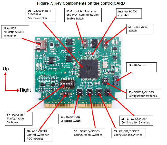
 At present, each switch of Control Card is ON / OFF as shown in the picture.

A yellow arrow pointing up means the switch is up, and a down arrow means the switch is down.

I want to program TIDA-01604 without USB 5V power.
In other words, I want to BOOT with flash memory.
To boot to flash memory, read the datasheet and circuit diagram. You need to give S1 switch to GPIO24 and GPIO32 without any other configuration or setting.
In the picture I sent you, let me know if you have to put both S1 switches up or down.
S1: I would appreciate it if you let me know.

  • Jaeyup,

    The reference guide, which contains the picture you have shown, should contain this information. 

    Please look at "Table 2. Getting Started Reference". The fourth column is for stand alone boot(which includes boot from flash). Please check that you have configured S1:A correctly.

    For flash boot mode Table 4 indicates that S1 needs to have both switches in the "UP" position. 

    Regards,
    Cody 

  • Thank you for answer.
    In the photo I've uploaded, let's talk about the buttons on the blue square boxes S1 and S1: A.
    To use it as a flash memory, the S1 switch is flipped 180 degrees, unlike other switches. On the photo, the two buttons are facing down, and the S1: A switch is on the photo, the left switch is down, and the right switch is up?

    And another question.
    Even if Phase Shedding is disabled in main.cfg, does it make 3-phase operation in pfc1ph3littpl.c code?

  • I recognize your confusion. The diagram that you have indicated above explains how "up" and "right" are orientated.

    Please note that all directional instructions are in reference to the controlCARD as a whole, not the individual switch placement.

    If you are still having trouble there is a detailed description for both S1 and S1A in Table 3 "Hardware References" of the same document. This will tell you verbosely which direction relates to which logic state.

    jaeyup jung said:
    Even if Phase Shedding is disabled in main.cfg, does it make 3-phase operation in pfc1ph3littpl.c code?

    Unfortunately I am not familiar with the phase shedding code that you are referencing. I would recommend that you ask unrelated questions in a separate thread, this will ensure that you get the best support.

    Regards,
    Cody