This thread has been locked.

If you have a related question, please click the "Ask a related question" button in the top right corner. The newly created question will be automatically linked to this question.

WEBENCH® Tools/TPS61178: TPS61178 on troubles.

Part Number: TPS61178

Tool/software: WEBENCH® Design Tools

Hi folks!

I've a trouble with a DC/DC TPS611781RNWR device. I've configured it as step-up from 2.7V - 4.2V to 6V, from a LiPo.

I want to feed two DC motors with about 1A each one. I've designed it with the reference values from the WEBENCH. 

The circuit looks okay, and the voltage without load it's 6.04V, so it's okay.

But, the problems come when I turn on one motor, the current isn't enough to run it, and the voltage goes down near to the main voltage input. From 6.04V to 3.83V, when the main is 3.7V.

I can imagine, that the problem is in the DC/DC current limit resistor. It doesn't generate enough current to feed the motors, and that's why the step-up doesn't work. But, certainly, I don't really sure what's happening.

I attach here the reference configuration from the WEBENCH.

My schema...

If someone need more information, I don't have any problem to upload it.

Thanks in advance!

  • HI Jorge:

    The output capacitor is too small. Please add 40uf there.

  • Hi Minqiu,

    Many thanks for your quick answer!

    I don't really sure if adding a 40 uF capacitor, the motor will have enough energy to doesn't carry out the DC/DC.

    If you check my schematic, I've added 10nF and 100nF to create a little fiitler and next, I've place a fuse. I suppose that you recommend to add there the 40 uF capacitor. Although, if you check the in the motor control part, I've placed a 220uF electrolytic capacitor in parallel for each motor. So, capactiance and "energy fuel" could be enough.

    I was trying to do some test, changing the divider resistor to obtain a little bit more voltage, but the result is the same. The DC/DC goes down the main voltage minuss the diode voltage, so that's mean that it's in open state, right??

    Also, I changed the RIimit, and I didn't obtain more current neither.

    So, the last thing that I could test it's to change the RSync, to check if the problems come from the DC/DC oscillation frecuency.

    I going to do some wave measurements and attach you here the response. I hope it could help. Also, I share with you the PCB layout .

    Best regards,

    Jorge,

  • Hi Jorge:

    Thanks for your information. The 10n+100nf is too small even there is large cap after the fuse. You can replace the 10nf with 10uf. Otherwise the circuit can't estimate the noise caused by switching well. As the fuse and long trace has additional impedance. 

    But it maybe not the root cause. It's prefer to check the waveform about Vin, Vout, SW, and better with current of the coil.

    Besides, is it easy to use a resistance to simulate the loading? If so, you could also try the performance with resistance load. It will do some help for debug. 

  • Hi Minqiu,

    Thanks for your reply. I replaced the both capacitor for two of 10uf each one. But it didn't improve the response of the boost. It continued leaving down the voltage to Vin less diode voltage.

    So, I'm thinking in solder a new board with that new capacitor values. Also, I'm thinking in replace the 220uF for 330uF with the same layout. Maybe, it could be better to have more energy to the motors.

    I'm a little bit confused because this device it can give until 20V 10A, it means 200W, I understand that I need an external FET, but my design needs 6W for each motor, so it's less than 10% of the available power. Even without FET.

    I'll try to recollect the Vin, Vout, SW, and current of the coil waveforms during this Friday, but I'm really busy this week, so, maybe the next week I'll be available to upload the debugging test, loading the device with different resistors. Notice, the motor needs 6V 1A, so it means that the internal coil resistor should be 6 ohms. I don't now if it helps, and if you can also try it in your lab with the same values.

    I'll notice you.

    Thanks for your support.

    Best regards,

    Jorge.

  • Hi Jorge:

    I don't think it will do significance help just replace the 220uF to 330uF. As TPS61178 has the enough capability to support 6V/2A.

    Jorge De Castro said:
    I'm a little bit confused because this device it can give until 20V 10A, it means 200W, I understand that I need an external FET, but my design needs 6W for each motor, so it's less than 10% of the available power. Even without FET.

    It's incorrect. The TPS61178 can handle 20V, or 10A. But it's hard to handle 20V*10A, mainly limited by thermal dissipation. And the converter will go into thermal shutdown. But it's another story than your case.

    We did the test at Vin=3V, Vout=5V, which is similar to your case. The converter can supply 3A loading. 

    I prefer to do deeper analysis after get the waveform. Besides, do you have the current probe? If you do, please measure the current of the inductance in the same time.

  • Hi Minqiu,

    If you think that with 220uF is enough energy, I'll not change it. Otherwise, I'll solder a new PCB only to do measurements on it.

    About the waveforms, I can measure Vin, Vout and SW. I don't have current probe to my oscilloscope, so, what can we do with the inductance's current?

    I'm thinking to do the test with a potentiometer, simulating different loads. Finally, with the 6 ohms motor load.

    Thanks for your support.

    I hope resolve it ASAP.

    Best regards,

    Jorge.

  • Hi Jorge:

    If you don't have the current probe, it's a little difficult to analysis. But never mind, let's check other factor at first. 

    It will do some help if using a resistance load, as we can obverse the output current according to the voltage drop. (...But still not the coil current.)

  • Hi Minqiu,

    Finally, I'll do the test on Monday.

    I've found in my home lab a LEM 55P current sensor. I don't know if we can work with it to do the coil measurements. 

    I leave you here the datasheet: https://www.lem.com/sites/default/files/products_datasheets/la_55-p_e.pdf

    I don't really sure, but the actually current probes are practically the same, right?

    I'll notice you with the waveforms without the current of the coil. But think in the LEM 55P, maybe it could help us.

    Also, I was thinking in send you a couple of PCBs to do the test if it's possible, and maybe more easy to you. It could be great have this option.

    Best regards,

    Jorge.

  • Hi Jorge:

    I'm not very familiar with LEM sensor, but I just found the bandwidth is 200khz, which may not enough.

    Actually, the most thing I worry about is the Cout. Secondly,  the load maybe larger than what we think, or the Vin may drop a lot during this period.


  • Hi Minqiu,

    Honestly, I don’t read the full datasheet, I only checked the max current.

    I’ve space to two change the two output capacitors for another 0603 bigger capacitors. I can change it for the value that you recommends me.

    I’ve measure the load and it’s 6 ohms, at least the motor impedance, although, the full track impedance could be greater.

    The Vin comes from a 30V 10A power supply, although the PCB will be supply by a one cell LiPo battery. But I don’t try it at the moment, because I think the results will be the same.

    How about send you the PCB? Do you think that could be possible?

    Have a nice weekend.

    Best regards,

    Jorge.

  • Hi Minqiu,

    I've tested the device as I noticed you the last week.

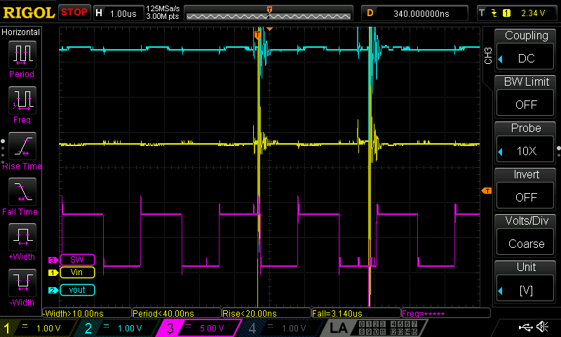
    Here, I leave you the waveforms:

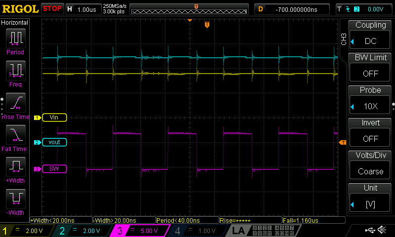
    That's the response without load.

    VIN = 3,75V

    VOUT = 6,4V,

    SW = 500 kHz.

    So, it looks right.

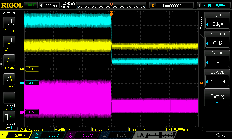
    Now, the response with the 6 ohms load.

    I've opened and closed the mosfet during a little time, and as you can appreciate the Vout goes down and SW changes the frecuency, and the Vin doesn`t change so much.

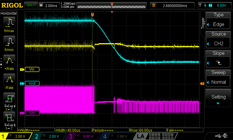
    I've tried to zoom it, and here is the result...

    During a short time, the device turn off the boost, and when it tries to start again it can't increase the voltage.

    What do you think about it? What do you recommend me? 

    Thanks for your support.

    Best regards,

    Jorge.

  • Hi Jorge:

    Sorry, full time meeting these days....

    According to the waveform, the Vin drops obviously. I wonder if it catches the UVLO. Can you test the circuit again with a power supply?

  • Hi Minqiu,

    I did the test with a power supply.

    The Vin didn't drop signficantly, maybe you have been confused with the Vout. The Vout droped to VIN less diode voltage. That's why every time whenI try i,t the internal mosfet goes to open state.

    I was reading in the Forum, that some guy do the same test and he got the same result than me. But the solution is closed. Check the link: https://e2e.ti.com/support/power-management/f/196/p/772833/2905327?tisearch=e2e-sitesearch&keymatch=TPS61178#2905327

    I attach you here a video with the simulation check it.

    Click here to play this video

    Maybe, the device it's entering in hiccup mode??

    I'm available to do the each test that you need, 

    Thanks for your support.

    Jorge.

  • HI Jorge:

    The yellow signal is the Vin right? It drops obviously before Vout drop. The output voltage of power supply is 3.7V, however the cable is so thin and the voltage drop caused by cable impedance shouldn't be ignored. 

    Please zoom in the Vin signal (Time and Amplitude) and to check if it catch the UVLO .

    It doesn't look like hiccup, as the hiccup will recover around 90ms, much longer than what shows in your waveform. 

  • Hi Minqiu,

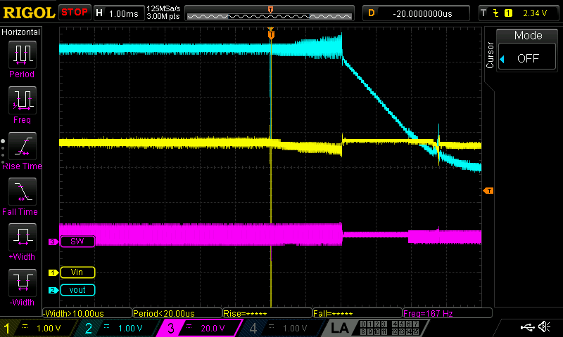
    I was testing again and you was right. The Vin drop off until UVLO. I've a coupled of picture about it. But if check in the future, when the Vout is dropping, the VIn has again the 3.7V, so why it doen't turn on again??

    The datasheet says that when Vin is 2.7V it starts again.

    I'm going to feed the device with a LiPo 1 cell battery, and the result is the same than now. So, have I to increase the wire diameter? Also the connector? I'm a little bit confused with the thin of the wire.

    Tell me what's the next step. 

    Thanks for your support. I'm drainning the time to finish the PCB project, and I don't like to change this DCDC for other device. Has any option solve it faster??

    Best regards,

    Jorge.

  • Hi Jorge:

    I'm sorry that I'm also confused why it doesn't recover. There may several issue happen together. You can soldering huge Al-cap to Vin side to keep the input voltage stable.

    Below are some steps may help to debug:

    1. Check the component are soldering well. Especially the current limit resistance, and the output capacitor (22uF or 47 uF MLCC).  And better replace a new IC, just in case of it's damaged during the test before.

    2.  Remove the load after Vout drop, to check if it can recover. And record the waveform 

    3. Zoom in the switching waveform after Vout drop. And record the input current.

  • Hi Minqiu,

    I've soldered a new PCB following your recommendation. The component are solder okay, and the values are nearby the same as the WEBENCH. Certianly, I cannot add 3 capacitor, becouse I don't have enough space for them, although, I've increased the capacity value.

    I've been testing with the power supply and the result it's the same. The dc/dc cannot generate enough power to the loads.

    As you commented, that the wires could be a problem, although I dismissed the idea at the first moment, I decided to replace the DUPONT wires to a 2.5mm wire. The result, magically, it starts to work!!!

    I increase the diameter of the battery wires, and it's working!!!

    I want to do some measurements with the oscilloscope and attach you it.

    I've checked that the device cannot generate power if the VIN is downside 3.35V. I don't know why, because I was sure that the device admitted until 2.8V, but we can disccuss it in the future. In evey case, the battery could be damaged if I forced it to work downside 3.6V.

    I want to do some test, before finish the issue, if it does not matter you. 

  • Hi Joege:

    It's glad to hear you got some discover. :-)

    The huge input capacitor I mentioned before is just for test, not production. It's for making the Vin stable. Yes, make a batter connection with short wire can reduce the parasitic impedance of the cables. Otherwise, the parasitic inductance and resistance will cause the obviously voltage drop as we observed before. 

    The device can support Vin=3.35V if the current doesn't reach the limit.(Which is determined by the Rlimit). We can discuss it later.