Hello, everyone
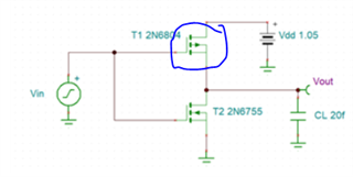
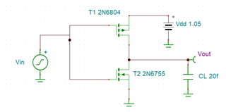
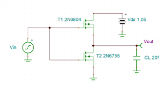
I want to simulate the waveform of CMOS inverter, but the result is different from what I expect.
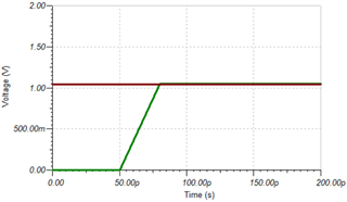
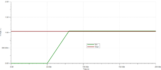
Why does the output always maintain high voltage?
Where's the problem in my circuit?
thank you
Hello, everyone
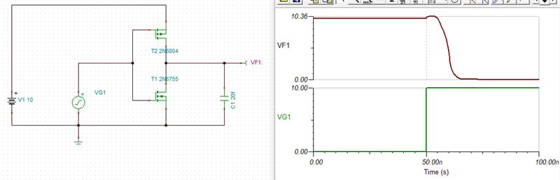
I want to simulate the waveform of CMOS inverter, but the result is different from what I expect.
Why does the output always maintain high voltage?
Where's the problem in my circuit?
thank you