Hi Experts,
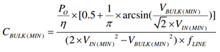
I am interested in using just the LLC stage and the output SR stage for a 600W DC-DC design. How would I calculate the input capacitance if I do not use a PFC stage?
Regards,
Gautham Venkat
Hi Experts,
I am interested in using just the LLC stage and the output SR stage for a 600W DC-DC design. How would I calculate the input capacitance if I do not use a PFC stage?
Regards,
Gautham Venkat