This thread has been locked.

If you have a related question, please click the "Ask a related question" button in the top right corner. The newly created question will be automatically linked to this question.

TIDA-010242: TIDA-010242 NORMAL OPERATİON

Part Number: TIDA-010242
Other Parts Discussed in Thread: LM5069, LM7480

Hi;

About the TIDA-010242 MIL-STD-1275 referance design curcuit;

I am traying to understand how does curcuit work for normal operation.

I am consederating to use this curcuit into my project as a protection curcuit of input power however my design have an 9-36V input range , if I use this curcuit as a input protection line , will my design work properly ?

How can I set the input range values in my design by using this referance curcuit?

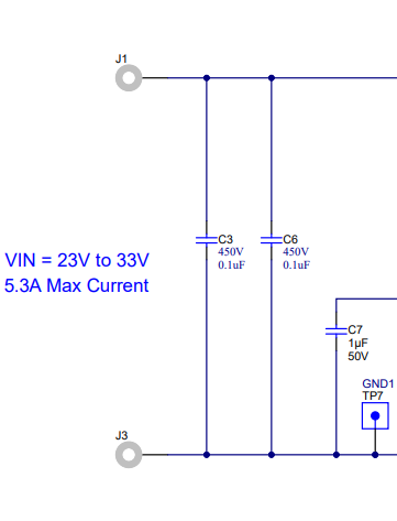
I am confused with this page that I shared below:
Waiting your answer,

Sincerely,

  • Hello and happy new year, thank you for your patience.

    The operational use of this circuit is a clamping circuit to protect against the surge and spike events that are outlined in the MIL-STD-1275E event.  So during normal operation, as long s the UVLO or OV conditions aren't broken then the voltage will be passed through. For example, 28V is the nominal voltage and fits within the range, so the output will se 28V. 

    During an OV event, the clamping circuit will clamp the voltage to 33V. So if the input gets to lets say 100V then the output will see 33V during that event. You can see in figure 3-9 of the design guide that during the whole event that it goes up to 100V and comes down, the output doesn't change at all and stays steady at 33V.

    For a UVLO situation the output will shut off for protection. 

    To set the limits of the UVLO, OV, and the output clamping voltage there are three places that you need to adjust. 

    To set the UVLO limit, you need to adjust R6 and R8, the resistor divider for the UVLO pin on the LM5069. Follow the datasheet for the LM5069 to calculate the resistor divider needed for  the 9V setting.

    To set the OV setting there are two places to set it. The first is the resistor divider of the LM7480 set to the OV pin, R2 and R4. That will set your upper limit for when the LM7480 will start clamping. The other component you need to adjust is the zener clamping diode D4 for the LM5069 circuit. This sets the output clamping voltage during any surge events. Currently the diode settings have it clamping to 33V, but can be adjusted by choosing a zener diode with a higher voltage rating. For more information on the clamping circuit please refer to this app note: LINK

    Thank you 

    Albert

  • Thank you for your reply.

    Have a nice day.