This thread has been locked.

If you have a related question, please click the "Ask a related question" button in the top right corner. The newly created question will be automatically linked to this question.

PMP20859: Seamless Failover

Part Number: PMP20859
Other Parts Discussed in Thread: LM5020, TPS3808

Hi TI,

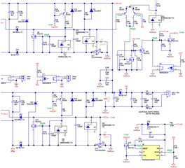
Is the reference design of PMP20859 able to output Vout with only Aux 48Vdc input and with disconnected PoE input? The reason asking this is because Vout would be 0V initially when PoE and Aux input are disconnected respectively. When only Aux input is connected, Q9 'gate' would be high and pull 'SS' to low, which subsequently prohibits U7 to operate and output Vout. This condition would not happen if PoE input and Aux input are connected, and then PoE input is disconnected. Because Vout is ON and pulls down Q9 'gate'.

Regards,
KK

  • KK,

    Yes, PMP20859 will work with just the AUX input.  If neither PoE input is connected, both Q5 and Q6 will be off.  Q12 will be off and Q10 will be on, which then turns off Q9.  This allows the SS of the LM5020 to work with just the AUX input.

    Thanks,

    David

  • Hi David,

    My understanding is different. When Aux is at 48V, pin-1 of U6 is high, AUX_OUT is low, Q14 gate is high, PG2 is low, Q12 gate is high, Q10 fate is low, Q9 gate is high and lastly SS is low. The green logic is labelled in schematic below for clearer illustration.

    Regards,
    KK

  • KK,

    With the CT pin open, the TPS3808 has a 20msec typical delay (12/20/28msec) from the SENSE being within range to the RESET pin asserting.  This allows the converter to turn on and U2 disables Q9.  From the test report the turn on time for the output is approximately 5msec.  I just measured this on a board...the delay time was right at 20msec.

    Thanks,

    David

  • David,

    This makes me clear. TI uses the longer delay of RESET signal to turn on the output with Aux input.
    A side question - normally TI provides Soft-start time in equation in controller datasheet. However, I could not find it in LM5020 datasheet. Do you know where we could find this info?

    Regards,
    KK

  • David,

    According to the e2e forum, LM5020 soft-start time could be approximated as (Comp + 0.55V)*Css/10uA. From LM5020 block diagram, there is a pullup to 5V on Comp pin. Thus, inserting 5V into the equation provides (5 + 0.55)*0.01u/10u = 5.55ms, which quite matches to the 5ms in the PMP20859 test report. However, LM5020 Evaluation Board, with same value of Css, output ramp up time is around 2ms according to Figure-3, -4 and -5. Is it because that Comp voltage is not fixed at 5V?

    Regards,
    KK

  • KK,

    That is correct.  Referring to the block diagram, the maximum voltage on the CS pin is 0.5V typical.  At the PWM comparator this voltage is compared to the output of a 2R/R divider, so there is 1.5V on the input of the divider.  Adding the 1.4V offset makes the COMP voltage for maximum duty cycle 2.9V.  The actual operating point is most likely something less than maximum duty cycle, which will result in a COMP voltage lower than 2.9V.  Also, these are all nominal values without tolerances taken into account.  Since the SS is ramping up the duty cycle, this limits the current available to charge the output capacitance.  The amount of output capacitance and DC load will also affect the start up time.  The main purpose of this type of soft start is to limit the current charging the output capacitance.  If you also want a more specific output voltage ramp up time it will take some iteration of the SS capacitor value.

    Thanks,

    David