This thread has been locked.
If you have a related question, please click the "Ask a related question" button in the top right corner. The newly created question will be automatically linked to this question.
team,
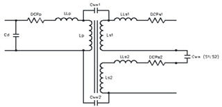
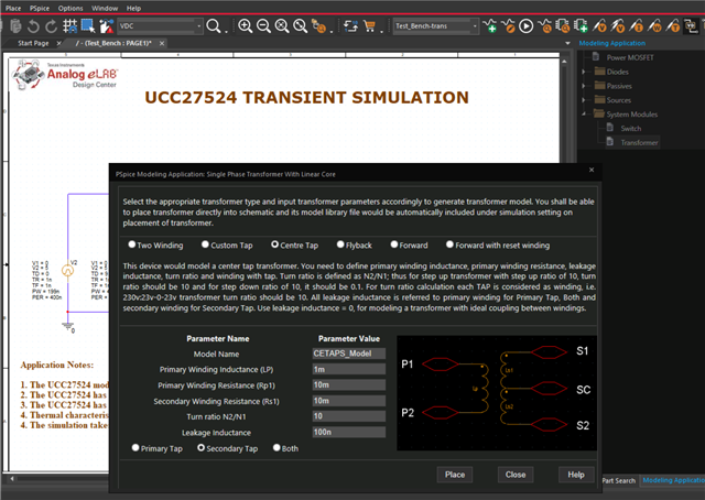
how do i add secondary winding to the transformer in PSPICE, as shown in below image.
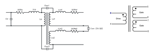
I need to model with custom values. Please guide.
Hi Mohammed,
You can try the as described in the following thread:
Here's another link as well:
https://e2e.ti.com/f/1/t/1279202
David
I did follow the thread. But i'm confused in the step of corelating K_break with inductors.
below is the figure i'm trying to replicate in my simulation.
Lp - 5.07mH
Ls1, Ls2 - 5.07mH.
Please advice.
Hi Mohammed,
Let me check in with some apps engineers who might have an easy answer.
David
Hi David,
Waiting for your response.
Also i tried simulating the gate drive circuit, it throws error. Can you please look into this also.
Thanks
Hi Mohammed,
I had no problem with the UCC circuit. That simulated just fine. I don't know why the gate circuit keeps saying that there's no ground.
I even removed the circuits for setting the Gate voltages and put 1V, 300V for mid, and 301 for the other gate. Still the same no ground warning.
I wonder if it's something in the C2 gate model.
If you are looking at a particular TI part, I can re-direct this to get apps support.
David
Hi David, I'm new to the pspice environment and I don't fully understand what you meant by it simulated just fine. What changes do I have to make to work ? Is there simulation settings or any, please guide in simple steps because When I try to simulate, it aborts the simulation. I basically need to plot Vgs of both MOSFETs.
And also assist me with the coupled inductors thing.
Thanks
You had 2 pages in your test bench. Page2 was the reference design for the ucc27524. I did a search and opened that reference design from the built in library and ran that simulation. It worked properly.
Your high voltage MOSFET, Page1, I could not get to simulate.
Still checking on the second tap transformer.
David
Hi Mohammed,
There is a built in transformer in PSpice.
You can access it when a schematic is open.
Go to Place, Pspice Component, Modeling Application
Then select System Modules, Transformer.
David
Hi david, What is available in PSpice is a center-tapped transformer, which is not similar to Pulse transformer, We need a separate second winding.
Help me with simulation and inductor or please connect me to the Expert who can guide on this ?
I need to finalise on the gate driver circuit.
Thanks
Let me check around. I didn't find anything specific to pulse transformers at Cadence's web site, pspice.com.
Hi Mohammed.
If you place the newly uploaded UCC27624 model in your circuit, and open its test bench, one of them is a pulse transformer circuit:
You said previously you had issues associating the inductors to the K_break? I just double clicked on the K symbol to open the property editor, and inserted these values:
I have found that you want to keep the coupling at 1 or 0.99, lower coupling leads to me having difficulties with convergence. I would skip the interwinding capacitance and leakage inductance until you have the ideal transformer working, then add them back one at a time. I believe the coupling factor should simulate the leakage inductance, but as long as you follow the dot notation I think discrete inductors should work as well.
Please let me know if any of this helps. I have simulations of 524 driving a half-bridge with a pulse transformer, but I never modeled the transformer with so much detail.
Thanks,
Alex M.
Thanks for the Update. Will work on this.
Also share 524 simulations, let me check that also.
Hi Mohammed,
Our expert is currently Out of Office and should get back to you by end of this week. Thanks for your patience and understanding.
Best,
Pratik
Hi Mohammed,
pulse gate drive-2024-01-04T15-50.zip
Please let me know if this works. It is just a very simple proof of concept, so don't pay much mind to the values and topology.
Thanks,