This thread has been locked.

If you have a related question, please click the "Ask a related question" button in the top right corner. The newly created question will be automatically linked to this question.

TIDA-01421: Peripheral RC Values Calculation

Part Number: TIDA-01421
Other Parts Discussed in Thread: TLV2316-Q1, LMV7275-Q1

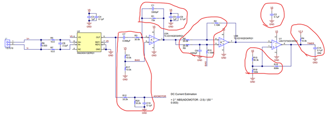
How the peripheral RC values(shown in red circles below) for TLV2316-Q1 and LMV7275-Q1 are calculated in the TIDA-01421 design?

  • The resistor (R) and capacitor (C) values will depend on the characteristics of the motor current ripple signal.  The goal of this circuit is to amplify only the frequency of the ripple signal, and attenuate the low-frequency (DC) and high-frequency (noise) content.  The op amp stages form a bandpass filter (blocks low-frequency and high-frequency) with passband centered on ripple fundamental frequency.  The comparator stage compares the output of the op amps to a voltage threshold, producing a pulse stream.  Ideally there is one pulse for each ripple cycle, allowing a simple pulse-counting function to keep track of motion.  A reference for filter design is https://webench.ti.com/filter-design-tool/filter-type .