This thread has been locked.

If you have a related question, please click the "Ask a related question" button in the top right corner. The newly created question will be automatically linked to this question.

TIDA-010062: Lab-4 Operation

Part Number: TIDA-010062
Other Parts Discussed in Thread: SFRA

Hello,

Need some help related to TIDA-010062.

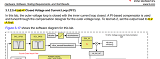
I tested Lab 4 after disabling the overcurrent protection from line 163 of ttplpfc_user_setting.h file

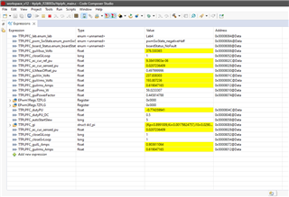
And was correctly able to get the output voltage of 390V(380 in the watch window) and the output current on the load was showing to be around 0.2.

(Load was set at 0.2A in CC as per the test process mentioned in the TIDUET7G)

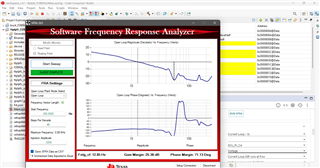
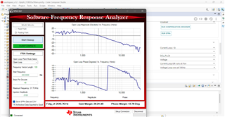
I also checked the SFRA for current loop and voltage loop, the SFRA readings looks fairly stable (kindly check attached screenshots)

However, while trying to increase/set the load current other than 0.2 Amps from load side in CC mode, the load current does not change and remains constant at 0.2Amps.

Why am I seeing such behavior?

Regards,

  • Hi SJZ,

    The PFC stage is controlling the CHOKE current and the output voltage, not controlling the output current. So the output current only depends on your E-load.

    If your output current is unadjustable, I am thinking your E-load was broken.

  • Hello,

    Thanks for the quick response.

    I have already confirmed the working of E-load by testing another ti PFC board(UCD3138 PFCEVM-026) and the current is correctly changing as per the change in load in CC mode. So the E-Load is working fine.

    I was unable to test Lab 3 of the TIDA-010062 so I was unsure about the stability of current loop.

    - However, with Kp=0.799 & Ki=0.0015, the Current-SFRA result outputs of Lab4 does indicate a stable enough system(as per the screenshot attached above) 

    Can this error be happening due current loop or Inductor?

    - Why is Lab4 specifically tested at CC of 0.2A according to the procedure in document - TIDUET7G?

    Regards,

  • Hi SJZ,

    Nothing special for 0.2A. Just hope to have a small load to the PFC stage, but not too heavy. You can use different, as 0.4A.

    I am thinking, maybe the E-Load is disturbed to be out of control, becuase TTPL has higher CM noise. I believe this doesn't happen when your PFC isn't running.

    Can you try with adding some CM filter between the output and the E-Load?

  • Hello,

    Yes, CM noise could be high, I have not populated the EMI filter on the board yet. 

    I can try adding the CM filter between output and E-Load, can you recommend a CM filter that would be good for this design?

    Thanks & Regards,