This thread has been locked.

If you have a related question, please click the "Ask a related question" button in the top right corner. The newly created question will be automatically linked to this question.

LM62460-Q1: Simulating LM62460 stability on PSPICE for TI

Part Number: LM62460-Q1
Other Parts Discussed in Thread: LM62460

Hi,

I'm not really using PSpice usually so I'm a bit unfamiliar with the software, but decided to give it a try to see how far I can get.

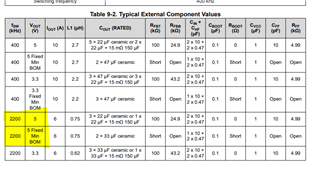
I checked this document ( https://www.ti.com/lit/pdf/sluaa51 ) which highlights how to do a loop stability test for a buck converter like the LM62460 on PSPice.

I did this to attempt to reproduce the example :

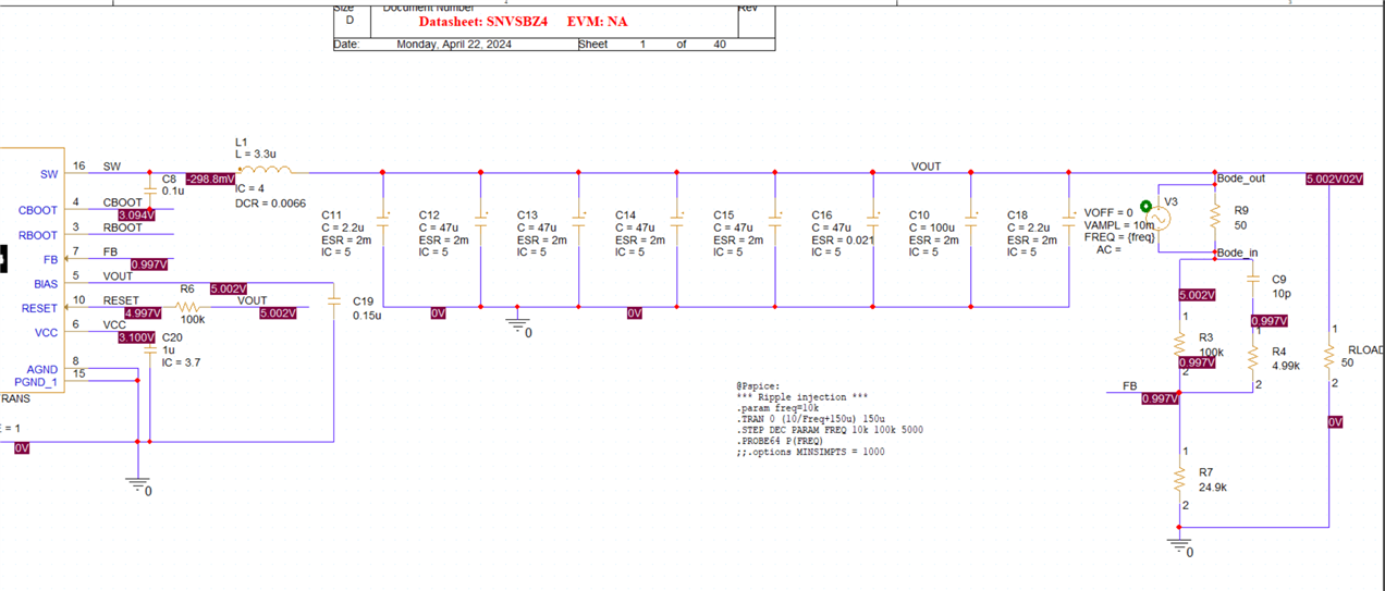
I get incredibly long simulation times. In fact it seems the thing is still at 0% after simulating for 2 hours in the simulation manager. Simulated only 10ms and it takes hours which just make the simulation completely unusable for rapid preliminary testing.

The "V3" source I assume in a VSIN source? I put the FREQ frequency sweeping from 10kHz to 100kHz with huge 5kHz frequency steps, yet the thing still takes forever.

Since the .TRAN directive is present, I used "Bias point" simulation profile and it seems after calculating the bias point the simulation goes on to transient analysis.

Am I doing this correctly or is the tutorial outdated? Seems the PSPICE for TI is a bit different from the PSpice UI inside shown in the PDF.

Could I get some help from TI to make this work and render correctly a bode plot with phase and gain?

Cordially

  • Hello,

    I am sorry to hear about your difficulties.

    SPICE can be a bit slow especially when data collecting on several nodes.

    To simulate loop response in SPICE, you need to have a different SPICE model with different style design and computation. You would want an average model which we don't have available for this product. You appear to be using the transient model used for transient analysis, not AC analysis.

    Based on your desire to get quick results, I would suggest you starting a webench design. In webench you can verify the loop response with your BOM quite quickly.

    If you encounter issues in webench let me know and I can try and help you work through the issues.

    https://webench.ti.com/power-designer/switching-regulator/create/customize?&VinMin=6&VinMax=24&O1V=5&O1I=6&base_pn=LM62460&AppType=None&Flavor=None&op_TA=30&origin=pf_panel&lang_chosen=en-US&optfactor=3&Topology=Buck&flavor=None&VoltageOption=None

    All the best,

    Marshall

  • Indeed I'm using the transient model. It seemed from SLUAA51 that the use of .TRAN would make it compatible with a transient model as the sweeping is done in transient simulation?

    I suppose my best bet with that SPICE model would be to evaluate the stability by provoking a step in current load and evaluating the phase margin through the oscillations following those steps? Would that work with that model?

    I'll give a shot at WEBENCH as well.

  • I haven't heard of that method before.  I don't think it will also be straightforward and  observing load transient in PSpice will probably not tell you much either. The model will run with very minimal output cap which isn't reflective of the device's actual behavior.

    I would advise webench. Hopefully that works for you.

  • I'm trying with WEBENCH but so far I'm a bit disappointed.

    When working with WEBENCH I set the current to the worse case scenario Iout because that's where I want to evaluate loop stability.

    However, when I write 0.1A in WEBENCH, the option to use CFF disappears! Why in the world would CFF not work with a low current?! It makes perfect sense actually to use CFF for better response with a lower current, when stability might be lower than at high current.

    DCM will happen at 0.1A I understand that so the converter will lose efficiency. But my current demands go from 0.1A to ~5A, I find that reasonable to get bode plots for both...

    Is there a solution to this? (get the bode stability plots for 0.1A just like I can for 5A, ***with CFF network***)

  • Hello,

    I understand the situation and am sorry to hear your frustration.

    When I advise on stability I recommend you evaluate across input voltage (right before the device goes into dropout and up to right before the device goes into min ton operation).

    For 5Vout, 2MHz switcher that would be ~7Vin to  28Vin.

    AC loop analysis is done for a linear control system which dropout behavior and min ton operation is not linear. The same goes for auto mode (DCM/PFM) behavior.

    With that said, you should also evaluate at full-load current for the device. 6A load. Load current does impact DC gain in the loop but has little effect on phase and gain margin from my experience. If it is stable at full load it will be stable with half load.

    As a starting point you can use are already proven out BOMs presented in the datasheet.