This thread has been locked.

If you have a related question, please click the "Ask a related question" button in the top right corner. The newly created question will be automatically linked to this question.

PMP22075: Questions of PMP22075

Part Number: PMP22075

Tool/software:

Dear sir,

 Would you please help on the following questions:

Q1:   Can you share the Gerber file with me?  appreciated that you can share the original circuit/PCB layout document if you can?

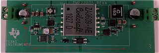
Q2:  Can you help check the size (L x W ) of the white box?  as following,

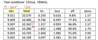
Q3:  In its test report (TIDT159-1.pdf),  on page 9,  11 Efficiency session,  as following,  do you know  the reason why Vout is not +12V when 9V input?  but this design input range is 9-60V.

Nice day!

Regards,

Jack

  • For Q1:  I can't open the Gerber file which download from TI.com.

    https://www.ti.com/tool/PMP22075#design-products

  • Jack,

    I was able to open the Gerber files on the web.  I have also attached themPMP22075REVB-GBR.zip here.

    The original design files are not available.

    The size of the white box is approximately 35x85mm.

    It looks like the duty cycle is being limited.  With DCL connected to RT the maximum duty cycle should be 80%.  With R16=143k, the overlap time is 400nsec...this seems high...I would expect it to be in the 100-200nsec range.  This overlap time will subtract from the maximum duty cycle.  The switching frequency is 160kHz (6.25us period), so 400ns overlap at each switching cycle will reduce the duty cycle by 12%.  Try reducing R16 to 51.1k for a overlap time of 145ns and see if the converter will regulate at 9V input.  If it does, check the efficiency and waveforms for any adverse affects of the lower overlap time.

    Thanks,

    David