This thread has been locked.

If you have a related question, please click the "Ask a related question" button in the top right corner. The newly created question will be automatically linked to this question.

LM5157-Q1: LM5157

Other Parts Discussed in Thread: LM5157

Tool/software:

Hi,

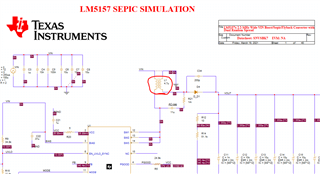
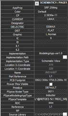
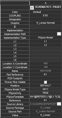
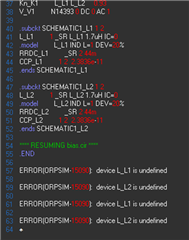
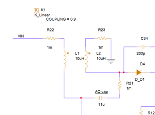
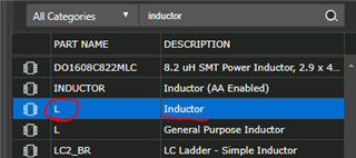
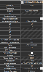
I am performing Sepic converter simulation in TI P Spice, the IC Used is LM5157 from TI. The selected Coupled inductor was PF0552.152NLT from Pulse Electronics. Pulse electronics do not have the model of Coupled inductor for simulation. So, i have measured the actual inductor parameters and trying to make the inductor model, I have tried with K linear and its not working for me.

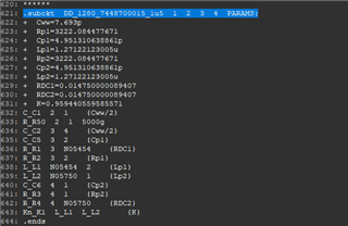
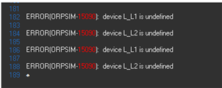
I am getting below Error,

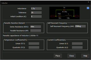
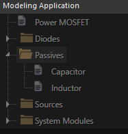
I have used the inductor from Modeling Application,

Please any one can help me how to create the Coupled inductor in TI P Spice.

Regards

Rayees K.E

  • Hi  Rayees,

    Since our expert of this device is out of office, please expect a late reply here.

    Regards

    Tao

  • Ok, please provide me some solution once he is available.

  • Hi Rayees,

    Thank you very much for your patience.

    Based on the error message it sound like there are different names for the inductors that do not match (L1 & L_L1).
    K_linear should be to correct tool to couple two inductors together, so it might be a naming issue after all.

    For convience, I can also suggests to use the SEPIC testbench that comes within the LM5157 PSpice download folder.
    You can simply copy the coupled inductor used here.

    Please let me know if additional errors come up.

    Best regards,
    Niklas

  • Hi Niklas,

    Thank you input. I have used the coupled inductor from TI Sepic reference simulation, it was working fine in my simulation also, but i need to change the parameter of the inductor based on My actual measured inductance data, but i was unable to change the parameter, is there any option to change the parameter of the inductor.

    Regards

    Rayees K.E

  • Hi Rayees,

    The model folder comes with a 'lm5157_trans_evm.lib' file. This file contains the external components of the schematic.
    A large portion of this file is encrypted as well, but the inductor parameters are visible:

    Best regards,
    Niklas

  • Hi Niklas,

    How to change the values in this inductor model. I have the measurement data for my actual inductor part of pulse electronics, i want to input this data to the model, is it possible to do so? then please help by providing the steps.

    Regards

    Rayees K.E

  • Hi Rayees,

    The inductance can be changed within the PSpice schematic.

    To change other parameters, I am afraid it is necessary to set up a new coupled inductor component as you initially tried.
    This would mean to go back to debugging the initial schematic and fix the naming errors.
    Another option would be importing a inductor model that is close to the Pulse Electronics part that has a simulation model.
    A guide on importing third party models can be found here:
    https://www.ti.com/video/6162754989001

    Please note that the PSpice model of LM5157 is a strongly simplified version of the physical IC. Influence due to noise, temperature or component variance is not implemented and Monte Carlo analysis is not possible.

    Best regards,
    Niklas

  • Hi Niklas,

    Thank you for your information.  

    I have again tried by 2 seperate inductor from modeling application library to create the coupled inductor, but i am getting the same error. For better understanding below are the steps i have followed,

    First open the Inductor from Modeling application and added the required parameter,

    Both the inductor i have made same and added the K Linear part,

    But i am getting the below error again,

    you can see I am not used any L_L1 reference in the schematic.

    Please provide your feedback to fix the naming error.

    Regarding the LM5157, i need to do the DC Sweep and AC analysis also, is it possible to in this model or any other model is available.

    Regards

    Rayees K.E

  • Hi Rayees,

    I cannot reproduce the errror you are receiving.
    I placed two regular inductors, placed resistors in series to simulate the ESR, then added K_linear and entered the L1 and L2 parameters.
    The simulation is running without errors on my side.

    Could you try to use simple inductor components and implement the ESR with an additional resistor and then try again?

    If this still does not work, could you send me your PSpice schematic so I can help debugging from my side?

    Thanks and best regards,
    Niklas

  • Hi Niklas,

    I have used the inductor from Analog library instead of Modeling application library and added the series resistor for ESR, now its running, the problem is here I am not able to input the SRF or the capacitance to match with the actual inductor. 

    Can you please help me, how to simulate the impedance curve of the created coupled inductor.

    Regards

    Rayees K.E

  • Hi Rayees,

    I am glad to hear that the circuit is running now.
    If the primitive inductor part has not option of defining a SRF value, I am not sure myself how to find a workaround for this.

    Is the SRF value close to the operation switching frequency of the device? I would focus on building the inductor as suitable as possible for the steady operation point.

    Best regards,
    Niklas

  • Hi Niklas,

    Switching frequency of the Sepic is 2.2 Meg, and SRF of the coupled inductor is 25 Meg. 

    One more thing i want to know how to simulate the Impedance curve of this coupled inductor.

    Also, is it possible to use the LM5157 model for DC Sweep and AC Analysis?

    Regards

    Rayees K.E

  • Hi Rayees,

    Unfortunately I have too little experience with PSpice inductors to answer the question on Impedance curve simulation.
    As this is a general PSpice question, I would recommend setting up a new thread for this to get insights from a PSpice expert.

    Regarding DC Sweep and AC Analysis:
    Yes, both is possible.
    A DC Sweep can be simulated within the transient model.
    For a AC/small signal analysis, it is required to use the average model for LM5157.

    Best regards,
    Niklas

  • Hi Niklas,

    Thank you for your support for resolving the coupled inductor modeling issue. 

    Previously i did the DC Sweep with LM5157 and observed it taking too much time to simulate, almost 2 days i waited for completing the DC Sweep simulation, finally it has showed error. Is there any settings to reduce this time.

    Regards

    Rayees K.E

  • Hi Rayees,

    I know that PSpice offers features of setting checkpoints for simulation states, to avoid restarting each simulation sweep from the start.
    I have not tried these tool myself yet.

    More descriptions on this can be found on the PSpice website. E.g.
    https://community.cadence.com/cadence_technology_forums/pcb-design/f/pspice/51079/pspice---tip-of-the-week-tired-of-running-lengthy-simulations-again-and-again-from-the-start#:~:text=Use%20Save%20Check%20point%20and,at%20different%20moments%20as%20checkpoints.

    Best regards,
    Niklas