- Ask a related questionWhat is a related question?A related question is a question created from another question. When the related question is created, it will be automatically linked to the original question.
This thread has been locked.
If you have a related question, please click the "Ask a related question" button in the top right corner. The newly created question will be automatically linked to this question.
Tool/software:
Hello, Teams.
The reference design has a pre-discharge circuit, but no pre-charge circuit. My queries are: -
1. Why isn't there a pre-charge circuit similar to the pre-discharge one?
2. If I need to create a pre-charge circuit, do I need to include another gate driver for the pre-charge MOSFET control?
3. The design does not include a charging current limiting circuit; I would appreciate if you shared a typical current limiting circuit to be integrated with this reference design.
Hi Ashenafi,
1. Why isn't there a pre-charge circuit similar to the pre-discharge one?
Because you can control the pre-charge current by charger CC loop, meaning you don't have to add extra serial resistor to reduce the charge current. So we don't add pre charge circuit here.
If I need to create a pre-charge circuit, do I need to include another gate driver for the pre-charge MOSFET control?
You can include one or change UCC27517 to a dual channel gate driver.
3. The design does not include a charging current limiting circuit; I would appreciate if you shared a typical current limiting circuit to be integrated with this reference design.
We don't have this circuit from our team, I heard TL494 can be used to build a current limiting circuit.
BRs
Kian
Because you can control the pre-charge current by charger CC loop, meaning you don't have to add extra serial resistor to reduce the charge current. So we don't add pre charge circuit here.
what do you mean by charger CC loop, can you please elaborate it a little bit?
You can include one or change UCC27517 to a dual channel gate driver.
Okay, I see.
We don't have this circuit from our team, I heard TL494 can be used to build a current limiting circuit.
Thank you but I do not think this PWM controller IC is the one that I am looking for designing the current limiting circuit, can you please ask other teams if they have a current limiting circuit applicable for this TIDA-010216 reference design?
Hi Ashenafi,
I mean the charger has constant current mode and constant voltage mode, so it can control the pre-charging/charging current when use CC mode. The charging behavior is totally controlled via charger.
Thank you but I do not think this PWM controller IC is the one that I am looking for designing the current limiting circuit, can you please ask other teams if they have a current limiting circuit applicable for this TIDA-010216 reference design?
Could you share you detailed specs requirements so I can send it to broader team.
Thanks!
BRs
Kian
Hi Kian,
Ok I got it.
the detail for the current limiting circuit is: -
1) For SOC (state of charge) under 90%, we want a maximum of battery charging current around 200A.
2) we want the charging current to be limited to 10A, when the SOC reaches 90% of the full charge.
Hi Ashenafi,
Sorry for the late reply because of business travel.
I checked internally, we are not able to offer 200A current limit circuit. You should limit this from charger side.
For the 10A current limit circuit, TL494 is a good option. Many customers use this as current limit circuit in low-side FET architecture. I am not able to provide the parameter calculation for you. You should do some simulation for it or initiate a E2E thread for TL494 for help.

BRs
Kian
Hi Kian,
It is okay.
I was looking at TL494 earlier, and this IC is only rated for a supply voltage of 41 V. However, my voltage requirement is 48V, hence this IC is not suited for my application. Could you recommend another one?
Hi Ashenafi,
TL494 is a PWM controller. The 41V voltage limitation is not the input voltage limitation. It can be used for 48V battery pack.
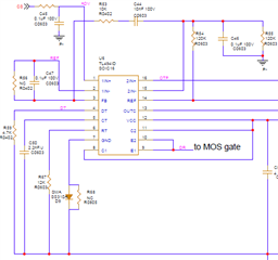
Below design file could help you better understand it:
You can find design information on the TL494 at www.ti.com/.../slva001e.pdf
There is a flyback reference design using the TL494 at www.ti.com/.../slva666.pdf
BRs
Kian

Hello, Kian.
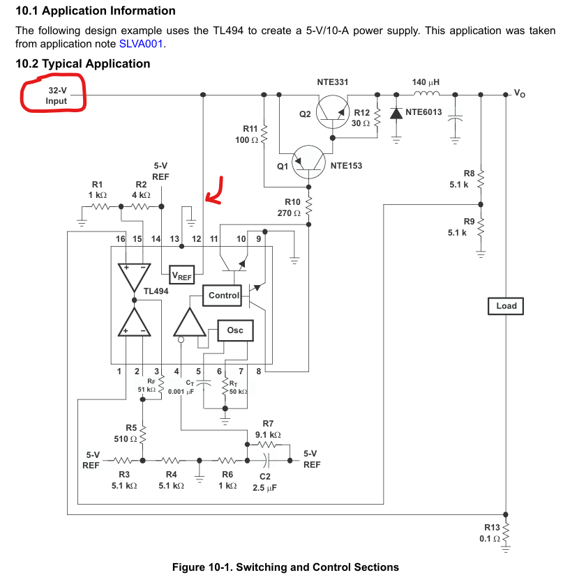
I browse through all of the accessible free resources. For example, look at this typical application circuit from the TL494 datasheet. The system is 32V, and this 32V is directly connected to pin Vcc of TL494, but I'm not sure if we can do the same for 48 V, as it's only rated for 41 V.
Hi Ashenafi,
You are correct. But you also can find below design from https://www.ti.com/lit/an/slva666/slva666.pdf

This part can be used for 48V but should need specific external components designs.
BRs
Kian
Hello, Kian.
I believe I did not explain my question clearly enough for you. I need this current limiter circuit for a battery management system, comparable to TIDA-010216, with an input voltage of 48VDC. However, as far as I know, the one you described above is an AC flyback converter, not a current limiter circuit. So let us all be on the same page and figure out a solution to this question.
Hi Ashenafi,
My answer is TL494 can be used as 48V 10A low-side FET current limit circuit. I saw many customers used this device in their battery pack. The flyback usecase is to show you you don't have connect 48V to TL494 VCC pin, you can divide it into a lower voltage or use the 12V power rail to power TL494.
But I can not offer you detailed circuit or calculation for this because we don't have such designs for now. I suggest you initiate another thread to ask TL494 product line for more design details.
BRs
Kian
HI Kian,
I asked my question on TL494 forum, and they suggest me this one. so, I need your help.
Hi Ashenafi,
I am not TI sales, do you have contacts of the TI fields sales/FAE in your region?
BRs
Kian
Hi Kian,
I don't have any. Is there any other option to find a solution for my question?
Hi,
If you need a total design, have to figure out who is FAE and TSR for your company. But if just specific questions regarding TL494, you can use E2E for sure.
Ryan
Hi Ryan,
I just want to make sure that this TL494 can be used for a 48V application system. If so , i need some proof, because it is rated for a maximum supply voltage of 41V only.
Hi Ashenafi,
As I said before, TL494 is a general PWM controller, you should not think you have to apply your system voltage to the TL494 power supply pin. You even can use the 12V supply for the gat driver in your system to power TL494. Please keep in mind it is a controller rather than a converter.
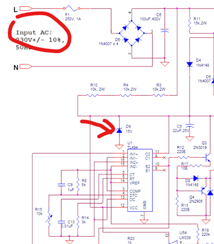
The proof is TL494 datasheet or https://www.ti.com/lit/an/slva666/slva666.pdf this design I mentioned which has 230V input voltage but clamp it to 15V to power TL494.
BRs
Kian
Hi Kian,
So, for my application I need to have an additional step-down converter IC before the TL494, right?
Hi,
In TIDA-010216, there already have 12V power supply can be used to power TL494.
Below is TL494 VCC range

BRs
Kian