This thread has been locked.

If you have a related question, please click the "Ask a related question" button in the top right corner. The newly created question will be automatically linked to this question.

UCC24624: Is there a minimum Rds(ON) for the controller?

Part Number: UCC24624
Other Parts Discussed in Thread: UCC24612

Tool/software:

Hello,

I have been going through some other controllers for a synchronous rectifier such as UCC24612 and I noticed that they have calculations for the minimum RDS(ON) of the MOSFET (topic 8.2.2.1 from the datasheet). I am currently using the UCC24624 for a GAN FET (with body diode) that has an Rds(ON) of 0.7 mOhms. Can that restrict or limit how the UCC24624 controller works? I have noticed that the controller and the FETs are heating up when the power goes above 600 W. When the load is 1kW, the temperature of the controller is near 62 Celsius (not sure if that is normal).

  • Hi Hugo,

    Could you share the waveforms at 600W and 1kW. I would like to look at the VDS1 (SR1 Drain voltage) and VGS1 ( SR1 Gate voltage) and VDS2 and VGS2.

    Could you also share the schematics and layout? What's the VDD of the SR controller? And Whats the output voltage of the LLC? 

    As the Rds goes down, controller turns off the gate pulses much faster so that most of the current goes through the body diode that should increase the temperature of FETs.

    To avoid the controller, heat up, you can use an external regulator from LLC output voltage to VDD of the SR controller so that regulator losses will be outside the controller not inside the controller.

    Regards

    Manikanta P

  • Hi Manikanta,

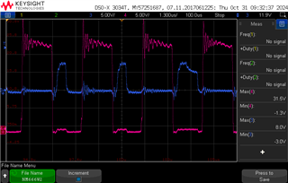
    This is the VDS1 and VGS1 at 600W:

    VDS1 x VGS1

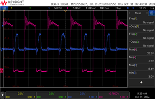
    and VDS1 and VGS1 at 1kW:

    The VDD is the same as the circuit's output voltage, which is 12V.

    My circuit on the secondary side is exactly like this image, with a 2.2R gate resistor on each FET:

    LLC Secondary side

    The SR controller turns off much faster, and the gate voltage is around 8 ~ 9V. The measurement of VGS is not directly connected to the controller's pins but from the gate to the source of the FET using a probe with tip and barrel.

    Unfortunately, I can't share the layout of my design, but I noticed that the sensing pin of VSS shares the same polygon as the load current path (which might cause the sensing to be noisy).

  • Hi,

    As you can see the controller is turning off the gate pulses much faster as the Rds on is very low. 

    62 degrees for the controller should be okay. 

    Regards

    Manikanta P

  • Hi,

    Is there something that could be done with the controller to fix this issue while working with very low Rds? If not, is there a minimum or recommended Rds value if using the UCC24624 as the controller?

  • Hi Hugo,

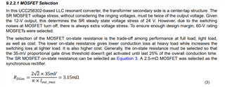
    The turnoff threshold can be increased with a resistor at the VSS pin. With the 20ohm, you already making use of that. So, you will have to use either higher Rds FET or a FET with the package of lower inductance to increase the gate turn on duration.

    The recommended Rds value can be found by equation given below:

    Regards

    Manikanta P