This thread has been locked.

If you have a related question, please click the "Ask a related question" button in the top right corner. The newly created question will be automatically linked to this question.

LM3102 designs do not work

Other Parts Discussed in Thread: LM3102, LM5009, LM3100

Hi everyone,

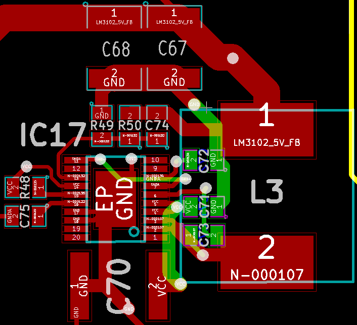
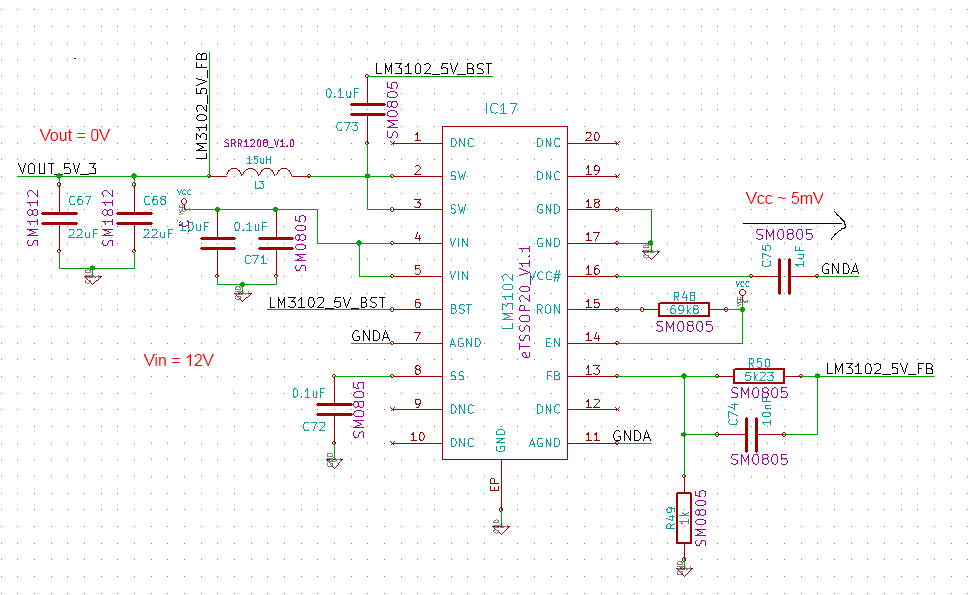
we use the LM3102 voltage regulator for 5V and 3.3V supplies and are having quite a hard time with it. Below you can see the schematics of the 5V supply with some measurements in red letters. We use the LM3102 according to the proposed webench design which also complies with the datasheet (e.g. the example on page 15 of the datasheet, except that we connected the EN pin to Vin). All values for external components have been adjusted according to the specification to match our problem.
But somehow the regulator is not working at all. The supposed voltage level of 6V for the Vcc-pin is not reached (we measure about 5mV at Vcc), even though the 12V input is applied properly. This is the same for both designs. In the simplified functional block description on page 10 in the datasheet it looks like the startup regulator starts working as soon as a sufficient Vin is applied and accordingly Vcc has to approach 6V by charging Cvcc. If this is not the case the UVLO circuit prevents switching. Could it be that we made a systematic manufacturing mistake? Another power supply on the same board with the LM5009 works fine, though. We soldered all parts in a standard reflow process and checked the PCB for short circuits. 


Any hints to possible causes for such a behaviour are very much appreciated.

Cheers

Jonas Witt

  • Is GNDA connected to GND in any way?

  • Hey Jonas,

    I reviewed your attached schematic and the component values look fine.  The only thing I can see maybe a problem if all the AGND pins are not grounded?  Can you share the layout of the LM3102?

  • Thanks for your replies.

    GND and GNDA are connected at exactly one point on the PCB. I double-checked the connections - everything seems fine on that side.

    Below is the relevant excerpt of the PCB. I blackened out unrelated parts. The PWR and GND layers are not displayed for more clarity.

    We are currently hand-soldering a test circuit as a last resort...

  • After some more researching I found the datasheet of the LM3100 of National (which seems to be the same part). They suggest to connect EN to Vcc via a pullup-resistor and give a warning about not connecting any voltages exceeding 7V. If one closely examines the maximum ratings in the TI datasheet one can see that the same is true for the LM3102. So both our LM3102 were probably fried by the voltage at the EN pin (which is directly connected to Vcc). In my opinion the datasheet that TI provides does a miserable job at informing about the right circuit for the EN pin. The typical application leaves out the EN pin and on page 3 in the pin descriptions even the statement "Connect a voltage higher than 1.26V to enable the regulator. Leaving this input open circuit will enable the device at internal UVLO level." is made. It should be suggested to keep the pin unconnected with a clear warning, since connecting a voltage seems to be the much more dangerous choice!

    We are currently validating this with the hand-soldered circuit...

    Update: Yes the LM3102 are fried. The hand-soldered circuit does work with the EN pin not connected.

  • Hey Patrick,

    I did not realized that this was the case so I took a functional LM3102 demo into the lab and did the same thing.  You are absolutely correct that it killed the part.  I'll pass on your message to the product line applications engineer and hope they can improve the datasheet.  Sorry for the inconvenience and let us know if replacing the ICs resolve this issue.