


Just curious how I might find (or create) a schematic model for the 556 series of timers (especially the TLC556) that is more than one (1) timer when added to a schematic..
The PCB Design tool displays a 14 pin DIP (as one would expect) from the single Timer 556 model the schematic version displays.
As a result, one can't create (and test) a 556 timer circuit (a cascaded timer, for instance) and then generate a PCB model since the schematic 556 is displayed as a single 555 timer with only the pins for a single 555 timer, not a dual timer.
See images below:
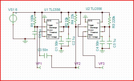

As you can see, the second 555 timer portion (pins 8-13) on the TLC556 footprint on the PCB isn't used.
Any suggestions?? Solutions??
Thanks.

